


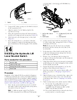


Install the Hydraulic Control Manifold
1.
Align the holes in the manifold with the holes on the
manifold bracket (non-HDX-Auto Workman models)
or right differential support (HDX-Auto Workman
models) as shown in
Figure 28
HDX-Auto Workman model shown
1.
Bolt (5/16 x 3/4 inch)
3.
Right differential support
(HDX-Auto Workman
models—shown); manifold
bracket (non-HDX-Auto
Workman models—not
shown; similar installation)
2.
Lock washer (5/16 inch)
4.
Manifold
2.
Secure the manifold to the bracket or the differential
support (
) with the 2 bolts (5/16 x 3/4 inch)
and 2 lock washers (5/16 inch).
9
Installing the Hydraulic Supply
Hoses
Parts needed for this procedure:
2
Hose (3/8 x 95 inch)
1
3-position switch
AR
Cable ties
Connecting the Hydraulic Lift Hoses
(3000 and 4000 series Workman)
Connect the extend and retract hoses that you disconnected
in
Disconnecting the Hydraulic Lift Hoses (3000 and 4000
series Workman) (page 8)
to the straight fittings in port A and
B of the hydraulic control manifold.
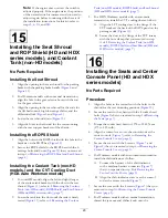
Installing the Hoses (non-HDX-Auto
Workman models)
1.
Install the straight fitting of the hydraulic supply hose
to the straight fitting in port A (extend) of the lift
cylinder control valve (
Figure 29
1.
Lift cylinder control valve
4.
Front of the machine
2.
Straight fitting (Port
A—extend)
5.
90° hydraulic fitting (Port
B—retract)
3.
Hydraulic supply hose
(straight fitting)
6.
Hydraulic supply hose (45°
fitting)
2.
Route the hose along the right side of the machine
along the path of the 2 hydraulic tubes (
) that
you removed in
5 Removing the Hydraulic Lift Lines
(page 8)
.
Figure 30
1.
Hydraulic supply hose
(extend)
3.
Front of the machine
2.
Hydraulic supply hose
(retract)
14


