


3.
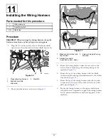
Install the 45° of the hydraulic supply hose to the
straight fitting in port B of the hydraulic control
manifold (
Figure 31
1.
Straight fitting (port
B—extend)
4.
Back of the machine
2.
Hydraulic control manifold
5.
Hydraulic supply hose
(straight fitting—retract)
3.
45° hydraulic fitting (port
A—retract)
6.
Hydraulic supply hose (45°
fitting—extend)
4.
Install the 45° fitting of the hydraulic supply hose to
the 90° hydraulic fitting in port B (retract) of the lift
cylinder control valve (
5.
Route the hose along the other hose (
) that
you routed in step
.
6.
Install the straight fitting of the hydraulic supply hose
to the 45° hydraulic fitting in port A of the hydraulic
control manifold (
).
7.
Secure the hoses to the chassis with cable ties as
required to support the hoses and prevent interference
with moving parts of the machine.
Installing the Hoses (HDX-Auto
Workman models)
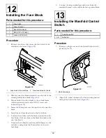
1.
Install the straight fitting of the hydraulic supply hose
to the straight fitting in port A (extend) of the lift
cylinder control valve (
Figure 32
1.
Lift cylinder control valve
4.
Front of the machine
2.
Straight fitting (Port
A—extend)
5.
90° hydraulic fitting (Port
B—retract)
3.
Hydraulic supply hose
(straight fitting)
6.
Hydraulic supply hose (45°
fitting)
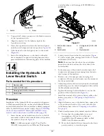
2.
Route the hose along the right side of the machine
along the path of the 2 hydraulic tubes (
) that
you removed in
5 Removing the Hydraulic Lift Lines
(page 8)
.
Figure 33
1.
Hydraulic supply hose
(extend)
3.
Front of the machine
2.
Hydraulic supply hose
(retract)
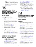
3.
Install the 45° fitting of the hydraulic supply hose to
the 45° hydraulic fitting in port B (retract) of the lift
cylinder control valve (
15


