background image

Toro General Commercial Products Warranty


A Two-Year Limited Warranty

Conditions and Products Covered

The Toro Company and its affi liate, Toro Warranty Company, 
pursuant to an agreement between them, jointly warrant your Toro 
Commercial Product (“Product”) to be free from defects in materi-
als or workmanship for two years or 1500 operational hours*, 
whichever occurs fi rst. This warranty is applicable to all products 
with the exception of Aerators (refer to separate warranty state-
ments for these products). Where a warrantable condition exists, 
we will repair the Product at no cost to you including diagnosis, 
labor, parts, and transportation. This warranty begins on the date 
the Product is delivered to the original retail purchaser.

* Product equipped with hour meter

Instructions for Obtaining Warranty Service

You are responsible for notifying the Commercial Products Dis-
tributor or Authorized Commercial Products Dealer from whom 
you purchased the Product as soon as you believe a warrantable 
condition exists. If you need help locating a Commercial Products 
Distributor or Authorized Dealer, or if you have questions regard-
ing your warranty rights or responsibilities, you may contact us at:


Toro Commercial Products Service Department


Toro Warranty Company


8111 Lyndale Avenue South


Bloomington, MN 55420-1196

 952-888-8801
 E-mail: 

[email protected]

Owner Responsibilities

As the Product owner, you are responsible for required main-
tenance and adjustments stated in your 

Operator’s Manual

Failure to perform required maintenance and adjustments can be 
grounds for disallowing a warranty claim.

Items and Conditions Not Covered

Not all product failures or malfunctions that occur during the 
warranty period are defects in materials or workmanship. This 
warranty does not cover the following:

Product failures which result from the use of non-Toro 
replacement parts, or from installation and use of add-on, 
or modifi ed non-Toro branded accessories and products. A 
separate warranty may be provided by the manufacturer of 
these items.
Product failures which result from failure to perform recom-
mended maintenance and/or adjustments. Failure to properly 
maintain your Toro product per the Recommended Mainte-
nance listed in the 

Operator’s Manual

 can result in claims for 

warranty being denied.
Product failures which result from operating the Product in an 
abusive, negligent or reckless manner.
Parts subject to consumption through use unless found to be 
defective. Examples of parts which are consumed, or used 
up, during normal Product operation include, but are not lim-
ited to, brakes pads and linings, clutch linings, blades, reels, 
bed knives, tines, spark plugs, castor wheels, tires, fi lters, 
belts, and certain sprayer components such as diaphragms, 
nozzles, and check valves, etc.
Failures caused by outside infl uence. Items considered to be 
outside infl uence include, but are not limited to, weather, stor-
age practices, contamination, use of unapproved coolants,

lubricants, additives, fertilizers, water, or chemicals, etc.
Normal noise, vibration, wear and tear, and deterioration.
Normal “wear and tear” includes, but is not limited to, dam-
age to seats due to wear or abrasion, worn painted surfaces, 
scratched decals or windows, etc.


Parts

Parts scheduled for replacement as required maintenance are war-
ranted for the period of time up to the scheduled replacement time 
for that part. Parts replaced under this warranty are covered for the 
duration of the original product warranty and become the property 
of Toro. Toro will make the fi nal decision whether to repair any ex-
isting part or assembly or replace it. Toro may use remanufactured 
parts for warranty repairs.

Note Regarding Deep Cycle Battery Warranty:

Deep cycle batteries have a specifi ed total number of kilowatt-
hours they can deliver during their lifetime. Operating, recharging, 
and maintenance techniques can extend or reduce total battery 
life. As the batteries in this product are consumed, the amount 
of useful work between charging intervals will slowly decrease 
until the battery is completely worn out. Replacement of worn out 
batteries, due to normal consumption, is the responsibility of the 
product owner. Battery replacement may be required during the 
normal product warranty period at owner’s expense.

Maintenance is at Owner’s Expense

Engine tune-up, lubrication cleaning and polishing, replacement of 
fi lters, coolant, and completing Recommended Maintenance are 
some of the normal services Toro products require that are at the 
owner’s expense.

General Conditions

Repair by an Authorized Toro Distributor or Dealer is your sole 
remedy under this warranty.

Neither The Toro Company nor Toro Warranty Company is
liable for indirect, incidental or consequential damages in
connection with the use of the Toro Products covered by this 
warranty, including any cost or expense of providing sub-
stitute equipment or service during reasonable periods of 
malfunction or non-use pending completion of repairs under 
this warranty. Except for the Emissions warranty referenced 
below, if applicable, there is no other express warranty. All 
implied warranties of merchantability and fi tness for use are 
limited to the duration of this express warranty.

Some states do not allow exclusions of incidental or consequential 
damages, or limitations on how long an implied warranty lasts, so 
the above exclusions and limitations may not apply to you. This 
warranty gives you specifi c legal rights, and you may also have 
other rights which vary from state to state.

Note regarding engine warranty:

The Emissions Control System on your Product may be covered 
by a separate warranty meeting requirements established by the 
U.S. Environmental Protection Agency (EPA) and/or the California 
Air Resources Board (CARB). The hour limitations set forth above 
do not apply to the Emissions Control System Warranty. Refer to 
the Engine Emission Control Warranty Statement printed in your 

Operator’s Manual

  or contained in the engine manufacturer’s 

documentation for details.


Countries Other than the United States or Canada

Customers who have purchased Toro products exported from the United States or Canada should contact their Toro Distributor (Dealer) 
to obtain guarantee policies for your country, province, or state. If for any reason you are dissatisfi ed with your Distributor’s service or 
have diffi culty obtaining guarantee information, contact the Toro importer.

Part No. 374-0031 Rev. D

Содержание 04052 Greensmaster 1000

Страница 1: ...Form No 3359 317 Rev D Greensmaster 1000 and 1600 Walk Behind Mower Model No 04052 Serial No 280000001 and Up Model No 04060 Serial No 280000001 and Up Register at www Toro com Original Instructions EN ...

Страница 2: ...ional information contact an Authorized Service Dealer or Toro Customer Service and have the model and serial numbers of your product ready The model and serial numbers are located on a plate on the rear frame Write the numbers in the space provided Model No Serial No This manual identifies potential hazards and has safety messages identified by the safety alert symbol Figure 1 which signals a haz...

Страница 3: ... Operating Tips 18 Maintenance 19 Recommended Maintenance Schedule s 19 Daily Maintenance Checklist 20 Lubrication 21 Greasing the Machine 21 Engine Maintenance 22 Servicing the Engine Oil 22 Servicing the Air Cleaner 23 Replacing the Spark Plug 23 Fuel System Maintenance 24 Cleaning the Fuel Filter 24 Electrical System Maintenance 25 Servicing the Interlock Switch 25 Brake Maintenance 25 Adjustin...

Страница 4: ...aring open sandals Thoroughly inspect the area where the equipment is to be used and remove all objects which may be thrown by the machine Warning Fuel is highly flammable Take the following precautions Store fuel in containers specifically designed for this purpose Refuel outdoors only and do not smoke while refuelling Add fuel before starting the engine Never remove the cap of the fuel tank or a...

Страница 5: ...n good working condition and all hardware and hydraulic fittings tightened Replace all worn or damaged parts and decals If the fuel tank has to be drained do this outdoors Be careful during adjustment of the machine to prevent entrapment of the fingers between moving blades and fixed parts of the machine Disengage drives disengage the cutting unit set parking brake stop engine and disconnect spark...

Страница 6: ...a maintenance adjustment keep hands feet clothing and any parts of the body away from the cutting unit attachments and any moving parts Keep everyone away To ensure safety and accuracy have an Authorized Toro Distributor check the maximum engine speed with a tachometer Maximum governed engine speed should be 3600 100 RPM If major repairs are ever needed or if assistance is desired contact an Autho...

Страница 7: ...ct hazard keep bystanders a safe distance from the machine 4 Cutting hazard of hand or foot stay away from moving parts 115 1613 1 Warning read the Operator s Manual 3 Thrown object hazard keep bystanders a safe distance from the machine 2 Warning remove the spark plug wire before performing any maintenance on the machine 4 Cutting dismemberment hazard of hand or foot stay away from moving parts 9...

Страница 8: ...ore servicing or performing maintenance 2 Cutting hazard of hand or foot stop the engine and wait for moving parts to stop 115 1614 1 Warning read the Operator s Manual 3 Thrown object hazard keep bystanders a safe distance from the machine 2 Warning do not operate the machine unless you are trained 4 Warning stay away from moving parts keep all guards in place 8 ...

Страница 9: ...115 1720 1 Forward 3 Neutral 2 Drive wheel 104 2618 1 Disengage lever position 3 Engage lever position 2 Parking brake 9 ...

Страница 10: ... of Compliance 1 Read or view before operating the machine Note Determine the left and right sides of the machine from the normal operating position 1 Installing and Adjusting the Handle Parts needed for this procedure 1 Handle 2 Cable tie Installing the Handle 1 Remove the bolt washer and lockwasher from the mounting pin on each side of the mower Figure 2 Figure 2 1 Mounting pins 3 Bolt and lockn...

Страница 11: ...Remove the hairpin cotters from the ring pins on each side of the mower Figure 2 2 While supporting the handle remove the ring pins from each side and raise or lower the handle to the desired operating position Figure 2 3 Install the ring pins and hairpin cotters 2 Installing the Kickstand Model 04060 Only Parts needed for this procedure 1 Kickstand assembly 1 Spring Procedure Note The fasteners a...

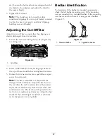
Страница 12: ...el onto the axle Figure 7 6 Pivot the wheel locking clip away from center of the wheel allowing it to slide farther onto the axle Figure 7 Figure 7 1 Locking clip 7 Rotate wheel back and forth until it slides completely onto axle and locking clip is secured in groove on axle shaft 8 Repeat procedure on opposite side of machine 9 Inflate the tires to 12 to 15 psi 574 to 718 Pa 4 Adjusting the Cutti...

Страница 13: ... Lever The traction drive lever Figure 9 is located on the front right side of the control panel It has two positions Neutral and Forward Pushing the lever forward engages the traction drive Service Parking Brake The service parking brake Figure 9 is located on left front side of control panel You can use the brake to slow or stop the machine Pulling the lever back over center will set the parking...

Страница 14: ...igure 12 1 Recoil starter 2 Kick stand Kickstand The kickstand Figure 12 is mounted to the rear of machine and is used to raise the rear of machine for installation or removal of the transport wheels Specifications Model 04052 Model 04060 Width 36 inches 91 cm 41 inches 104 cm Height 41 1 2 inches 105 cm 41 1 2 inches 105 4 cm Length with basket 59 inches 150 cm 59 inches 150 cm Dry weight with ba...

Страница 15: ...ure 13 1 Fuel tank cap 2 Fuel gauge In certain conditions gasoline is extremely flammable and highly explosive A fire or explosion from gasoline can burn you and others and can damage property Fill the fuel tank outdoors in an open area when the engine is cold Wipe up any gasoline that spills Never fill the fuel tank inside an enclosed trailer Do not fill the fuel tank completely full Add gasoline...

Страница 16: ...ts wheels on the ground If this is not possible then refuel such equipment on a truck or trailer from a portable container rather than from a gasoline dispenser nozzle If a gasoline dispenser nozzle must be used keep the nozzle in contact with the rim of the fuel tank or container opening at all times until fueling is complete Gasoline is harmful or fatal if swallowed Long term exposure to vapors ...

Страница 17: ...andle when rope is pulled out because rope may break or recoil assembly may be damaged 7 Move the choke to the Off position as the engine warms up Stopping the Engine 1 Move the traction and reel drive controls to the Disengaged position the throttle control to the Slow position and the On Off switch to the Off position 2 Pull the spark plug wire off of the spark plug to prevent the possibility of...

Страница 18: ...reen move the traction control lever to the Disengage position stop the engine and push the reel drive lever into the Disengage position 5 Empty the grass basket of clippings install the grass basket and commence transport operation Operating Tips Before Mowing Ensure that the mower is carefully adjusted and is set evenly on both sides of the reel Improper mower adjustment is magnified many times ...

Страница 19: ...d oil the air cleaner foam element More often in dirty or dusty conditions Every 50 hours Change the engine oil More frequently in dusty or dirty conditions Clean the fuel filter Every 100 hours Clean or replace the paper air filter element More often in dirty or dusty conditions Check the spark plug Every 200 hours Decarbon the engine Every 300 hours Change the air filter paper element Check the ...

Страница 20: ...the parking brake operation Check the fuel level Check the engine oil level Check the air filter Clean the engine cooling fins Check for unusual engine noises Check for unusual operating noises Check the reel to bedknife adjustment Check the height of cut adjustment Grease all fittings Touch up damaged paint Notation for Areas of Concern Inspection performed by Item Date Information 20 ...

Страница 21: ...oller Figure 14 2 on the reel bearings Figure 14 2 on the drum axles Figure 15 3 on the differential Figure 15 2 on the reel countershaft bearings Figure 16 2 on the belt idler pivots Figure 17 1 Wipe each grease fitting with a clean rag _ 2 Pump grease into each fitting until it begins to get difficult to pump the gun Important Do not apply too much pressure or grease seals will become permanentl...

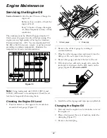
Страница 22: ... 40 will increase oil consumption Check the oil level more frequently when using them Checking the Engine Oil Level 1 Position mower so the engine is level and clean around oil level gauge Figure 19 Figure 19 1 Oil level gauge 2 Drain plug 2 Remove the oil level gauge by rotating it counterclockwise 3 Wipe the oil level gauge clean and insert it into the filler port Do not screw it into the port 4...

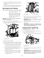
Страница 23: ...dirt but do not twist it because the foam may tear B Dry the foam element by wrapping it in a clean rag Squeeze the rag and foam element to dry it but do not twist it C Saturate the foam element with clean engine oil Squeeze the element to remove excess oil and to distribute the oil thoroughly An oil damp element is desirable Figure 22 1 Foam element 2 Paper element 5 Check the condition of the pa...

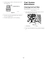
Страница 24: ...lb 23 N m 5 Install the spark plug wire on the spark plug Fuel System Maintenance Cleaning the Fuel Filter Service Interval After the first 25 hours Every 50 hours 1 Close the fuel shut off valve and unscrew the bowl from the filter body Figure 25 Figure 25 1 Shut off valve 2 Bowl 2 Clean the bowl and filter in clean gasoline and install it 24 ...

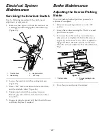
Страница 25: ...ion lever must not contact the switch 5 Engage traction lever and verify that the switch loses continuity Replace if required Brake Maintenance Adjusting the Service Parking Brake If service parking brake slips when operated an adjustment is required 1 Move service parking brake lever to the Off position 2 Loosen the retainer securing the V belt cover and pivot the cover open 3 To increase the cab...

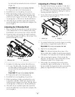
Страница 26: ...e 29 Important Do not over tension the belt B Tighten the nut to lock the adjustment 4 Install the belt cover by placing it in position 5 While maintaining a slight gap between the cover seal and the side plate install each mounting bolt until the threads engage in the insert The gap allows visual alignment of the bolts to the threaded inserts 6 After all bolts are installed tighten them until the...

Страница 27: ...over by placing it in position 5 While maintaining a slight gap between the cover seal and the side plate install each mounting bolt until the threads engage in the insert The gap allows visual alignment of the bolts to the threaded inserts 6 After all bolts are installed tighten them until the stand offs inside the cover contact the side plate Do not overtighten Adjusting the Primary V Belts 1 To...

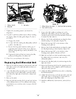
Страница 28: ...ions away to expose the belt Figure 35 Figure 35 1 Differential cover sections 3 Right rear bearing housing 2 Front clutch housing 5 Loosen the idler pulley mounting nut on the differential idler pulley and pivot the idler pulley counterclockwise away from the backside of the belt to release the belt tension 6 Remove the 2 bolts and locknuts securing the front clutch housing to the side plate Figu...

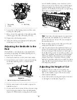
Страница 29: ...e on a flat level surface preferably a precision steel work plate 2 Place a 1 4 x 1 inch 0 6 x 2 5 cm flat steel strip approximately 29 inches 73 6 cm long under the reel blades and against the front edge of the bedknife to prevent the bedbar from resting on the work surface 3 Raise the front roller so only the rear drum and reel are on the surface 4 Firmly press down on the machine above the reel...

Страница 30: ... click at a time until the paper is pinched lightly when inserted from the front parallel to the bedknife which results in a slight drag when paper is pulled Figure 39 Figure 40 Note Each time the adjusting screw is rotated one click clockwise the bedknife moves 0 0007 inch 0 0017 cm closer to the reel Do not overtighten the adjusting screws 5 Check for light contact at the other end of the reel u...

Страница 31: ...snug against the bedknife This ensures the height of cut is identical at both ends of the bedknife 7 Tighten nuts to lock the adjustment Important To avoid scalping on undulating turf ensure that the roller supports are positioned rearward the roller closer to the reel Note The front roller can be put in three different positions Figure 44 depending on the application and needs of the user Use the...

Страница 32: ...and the bar and tighten the screws 3 Ensure that the bar and reel are equal distance apart across the entire reel Note The bar is adjustable to compensate for changes in turf conditions Adjust the bar closer to the reel when the turf is extremely wet By contrast adjust the bar further away from the reel when turf conditions are dry The bar should be parallel to the reel to ensure optimum performan...

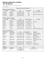
Страница 33: ...master 1600 0 125 0 25 inches 104 2646 HighCut Greensmaster 1600 0 25 inches and up Tees 93 9015 Low Cut Greensmaster 1600 0 25 inches and up Standard Greensmaster 1600 Rollers Standard and Optional Part Number Description Mower Diameter Material Comments 99 6241 Narrow Wiehle Greensmaster 1000 2 0 inches Aluminum Standard 0 2 Spacing 88 6790 Wide Wiehle Greensmaster 1000 2 0 inches Aluminum More ...

Страница 34: ...o 240 to 320 inch lb 27 to 36 N m 4 Tighten the jam nuts until the thrust washers just rotate freely 5 Tighten the spring tension nut until the spring is collapsed then back it off 1 2 turn 6 Adjust the bedbar refer to Adjusting the Bedknife to the Reel Backlapping the Reel 1 Remove the plug in the right reel drive cover Figure 50 Figure 50 1 Cover plug 2 Insert a 1 2 inch socket extension connect...

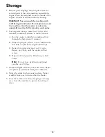
Страница 35: ...gine to distribute conditioned fuel through the fuel system 5 minutes B Either stop engine allow it to cool and drain the fuel tank or operate the engine until it stops C Restart the engine and run it until it stops Repeat on Choke until the engine will not restart D Dispose of fuel properly Recycle as per local codes Note Do not store stabilizer conditioned gasoline over 90 days 3 Check and tight...

Страница 36: ...t is not limited to dam age to seats due to wear or abrasion worn painted surfaces scratched decals or windows etc Parts Parts scheduled for replacement as required maintenance are war ranted for the period of time up to the scheduled replacement time for that part Parts replaced under this warranty are covered for the duration of the original product warranty and become the property of Toro Toro ...

Отзывы: