Setup
Loose Parts
Use the chart below to verify that all parts have been shipped.
Procedure
Description
Qty.
Use
Handle
1
1
Cable tie
2
Install the handle.
Kickstand assembly
1
2
Spring
1
Install the kickstand (model 04035 only).
Wheel shaft, right
1
Wheel shaft, left
1
3
Transport wheels (obtain separately)
2
Install the transport wheels.
4
No parts required
–
Adjust the cutting unit.
5
Grass basket
1
Install the grass basket.
Media and Additional Parts
Description
Qty.
Use
Operator’s Manual
1
Engine Operator’s Manual
1
Parts Catalog
1
Operator Training Material
1
Certificate of Compliance
1
Read or view before operating the machine
Note:
Determine the left and right sides of the machine
from the normal operating position.
1
Installing and Adjusting the
Handle
Parts needed for this procedure:
1
Handle
2
Cable tie
Installing the Handle
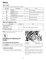
1. Remove the bolt, washer, and lockwasher from the
mounting pin on each side of the mower (Figure 2).
Figure 2
1.
Mounting pins
3.
Bolt and locknut
2.
Handle arms
4.
Hairpin cotter and ring pin
2. Remove the bolts and locknuts securing the bottom
of the handle arms to each side of the mower
(Figure 2).
3. Remove the hairpin cotters and ring pins securing
the handle arms to the rear of the frame (Figure 2).
4. Insert the handle ends thru the holes in the handle
arms and align the holes with the mounting pins
(Figure 2).
10


