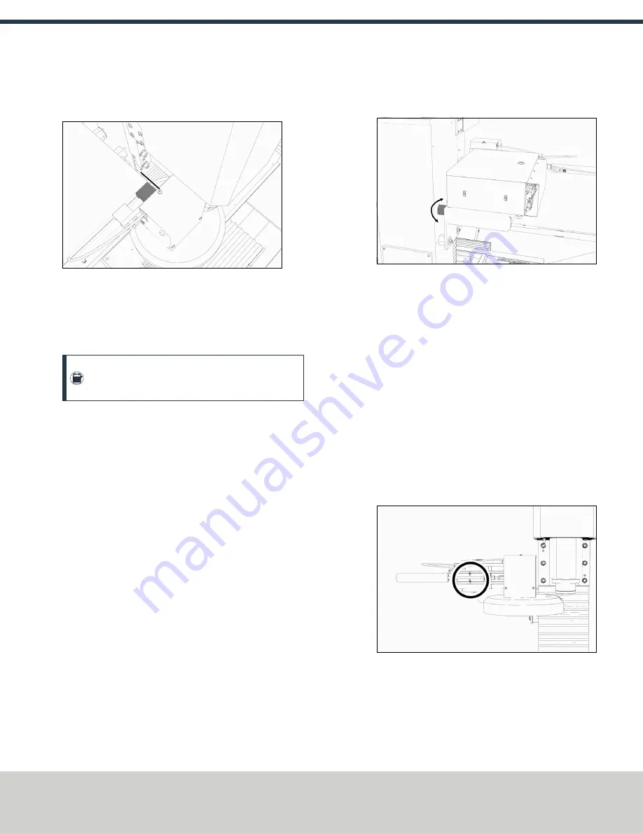
Figure 2-7: Tool tray moved in toward the spindle.
2. Make sure that the linear bearing on the ATC is flush with the
ATC main assembly.
Figure 2-8: Linear bearing flush with the ATC main
assembly.
3. Find a straight rod between 8 in. and 12 in. (203 mm and 305
mm) long. Verify that it's straight: roll it on a known flat
surface (like a granite surface plate).
Note:
You'll use the rod to verify that the ATC is
correctly installed on the mill, so it must be straight.
4. Put the alignment rod into a tool holder.
5. Put the tool holder into the fork so that the groove in the tool
holder slides into the fork, and so that the drive slot aligns
with the dog. Don't rest the tool holder on top of the fork.
6. Put a machinist's square on the machine table.
Examine Perpendicularity in the Y Direction
1. Make sure that the rod is perpendicular to the machine table
in the Y direction: compare the rod's position to the vertical
edge of the machinist's square.
l
If the rod is perpendicular to the vertical edge of the
machinist's square, go to "Examine Perpendicularity in the
l
If the rod must be adjusted, go to Step 2.
2. Loosen the flange nuts on the standoffs.
3. Turn the tilt standoff with an adjustable wrench, and slowly
pivot the ATC until the rod is perpendicular to the vertical
edge of the machinist's square.
Figure 2-9: Tilt standoff.
4. Tighten the flange nuts with a 13 mm socket.
5. Reexamine the alignment of the ATC in the Y direction. If the
rod isn't perpendicular to the vertical edge of the machinist's
square, repeat Steps 2 through 5.
Examine Perpendicularity in the X Direction
1. Make sure that the rod is perpendicular to the machine table
in the X direction: compare the rod's position to the vertical
edge of the machinist's square.
l
If the rod is perpendicular to the vertical edge of the
machinist's square, go to "Examine the Alignment of the
Carousel Door Opening" (on the next page).
l
If the rod must be adjusted, go to Step 2.
2. Loosen the two socket head cap screws on the linear rails.
Figure 2-10: Socket head cap screws on the linear rails.
3. Slowly pivot the linear rails up or down until the rod is
perpendicular to the vertical edge of the machinist's square.
4. Tighten the socket head cap screws.
Page 6
©Tormach® 2019
Specifications subject to change without notice.
tormach.com
TD10627: Owner's Guide: 770MX Automatic Tool Changer (ATC) (1019A)
TECHNICAL DOCUMENT


