Torishima Pump CAL Скачать руководство пользователя страница 11

CAL  Optional  Design 

- 8-   

The gland should be slightly recessed from the casing cover. The 

gland packing should be lightly tightened at the beginning. Then, 

re-tighten it after running the pump for a certain period. Adjust the 

gland packing so that liquid leakage from the gland is approx. 10 to 

20 cc/min. 

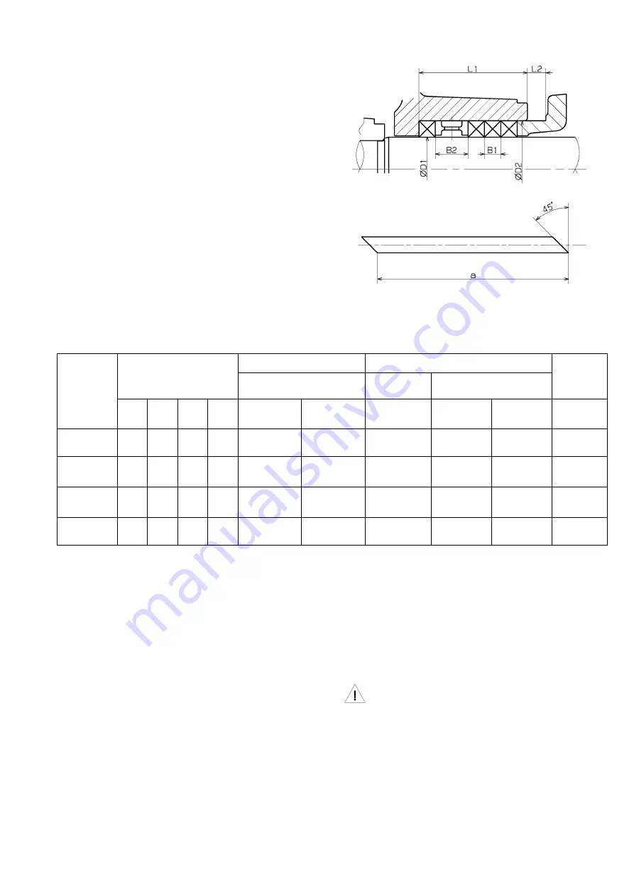
The dimension of the shaft seal and gland packing are shown in Fig 

3.2-2 and Table 3-1. 


Fig 3.2-2 


Table 3-1    the dimension of the shaft seal and gland packing 

Unit: mm 

Shaft size 

Shaft seal dimensions 

Quantity of gland packing 

Gland packing dimensions 

Lantern 

ring 

dimensions 

Lantern ring 

Molded part 

String-shaped part 

D1 

D2 

D3 

D4 

Provided 

None 

D1×D2×B1 

Thickness 

Overall 

length (a) 

B2 

25-360 

24 

40 

53 

24×40× 8 

100.5 

16 

35-470 

45-470 

32 

48 

53 

32×48× 8 

125.7 

16 

45-470A 

55-530 

45 

65 

65 

12 

45×65×10 

10 

172.8 

20 

65-530 

55 

75 

65 

12 

55×75×10 

10 

204.2 

20 

Use molded ring-shaped gland packing as much as possible. 


3.3.  Meters and gauge 

It is recommended that a pressure gauge or compound pressure 

gauge should be mounted to the pump body or the suction piping in 

proximity to the pump, and that a pressure gauge should be 

mounted to the discharge piping. These pressure gauges must be 

provided with gradations capable of covering about 150% of 

maximum operating pressure. Also connect a gauge cock to each 

gauge. When pumping a corrosive liquid, use an anti-corrosion 

gauge cock. When pumping liquid contains free matter or solid 

matter, use a proper strainer with the gauge cock. For the long life 

of each gauge, keep the gauge cock closed all the times, expect 

when it is opened to read the operating pressure. 

3.4.  Bearings 

Maintenance and inspection of the pump bearings are very 

important. Maintenance and control of bearings of each lubrication 

type are described below. 

3.4.1.  In the case of grease lubricated bearings 

Inspection and control of the bearing temperature and replacement 

of the ball bearings (3210) are required at an appropriate timing. 


Heat-resistant grease is sealed in the bearing. The 

maximum permissible temperature thereof is 

90 

degrees C max 

on the bearing housing (3300) surface 

or ambient 

temperature plus 55 degrees C max


The bearing replacement intervals vary depending on operating 

conditions. During continuous operation, the bearings must be 

replaced at an interval of approx. 9000 hours, as standard. In the 

case of short-time operation, it is recommended that the bearings 

should be replaced every two years. Further, it is recommended to 

Содержание CAL

Страница 1: ...PT TORISHIMA GUNA INDONESIA CAL END SUCTION...

Страница 2: ...allow any persons other than service engineers to engage in disassembly or repair or remodeling work 2 Never work alone and be sure to put on helmet safety goggles ear plugs safety shoes etc in confor...

Страница 3: ...t the specified position with mounting bolts 4 Maintenance 1 When carrying out the work for replacement of gland packing or mechanical seal be sure to turn OFF the motor switch and affix a tag indicat...

Страница 4: ...ge caused by the following 1 Operation of the pump under liquid quality density and temperature and running conditions which are deviated from those specified in the pump specifications 2 Pump damage...

Страница 5: ...rge nozzle and support foot The pump can be disassembled and internally inspected without removing the casing 1020 from the piping Refer to Table 0 1 for a representative Pump Sectional Drawing Table...

Страница 6: ...conditions refer to Section 6 P 21 Fig 0 4 2 Sectional Drawing gland packing grease lubrication Note 1 The above figure is one structural example Note 2 The structure of mechanical seal is different...

Страница 7: ...g 3300 0 4 5 Shaft The shaft components of each pump type are interchangeable with those of other pump As shown in Table 0 2 the shaft is available in six sizes which cover all models of the CAL pumps...

Страница 8: ...side 2 To check the rotational direction of the motor with the pump that uses a flanged flexible shaft joint remove the coupling bolts With the pump that uses a rubber shaft joint slide the couplings...

Страница 9: ...e installation be sure to check the following items for normality prior to starting If abnormality de found upon checking take corrective actions in accordance with the Troubleshooting Instructions gi...

Страница 10: ...nning And is the discharge valve kept closed 6 Is each bearing free from abnormal temperature rise 3 2 Shaft seal 3 2 1 In the case of mechanical seal type It is one outstanding feature of mechanical...

Страница 11: ...mounted to the discharge piping These pressure gauges must be provided with gradations capable of covering about 150 of maximum operating pressure Also connect a gauge cock to each gauge When pumping...

Страница 12: ...will remove dirt well When a new bearing is used replace all amount of lubricating oil after operation for the initial 300 hours After that the replacement interval should be 3 000 hours of operation...

Страница 13: ...ue is 1 0 mm The design value for the impeller whose material is SCS is 0 6 mm and the tolerance value is 1 2 mm If the tolerance value is exceeded replace the case wearing ring 3 6 When the pump is l...

Страница 14: ...ling and reassembling When rubber shaft joint is used When flanged flexible shaft joint is used The above figure shows an example of pump and motor configuration The type of configuration varies depen...

Страница 15: ...r wear and other damage of the element If an abnormal condition is found replace the element with a new one 13 Remove the both bearing covers 3600 from the bearing housing 14 Slowly pull the shaft out...

Страница 16: ...mp Including the running under the seal box pressure below the atmospheric bar Dry running will result in seizure trouble of the mechanical seal eventually causing not only the mechanical seal but als...

Страница 17: ...32 45 Fig 5 2 1 Construction of mechanical seal CA Note For order of additional spare parts designate the type of the mechanical seal as a set in order to ensure preferable seal effect Parts table of...

Страница 18: ...710 Seal cover 4751 Seat holder Unit mm Shaft size 25 360 24 44 5 35 470 45 470 45 470A 55 530 65 530 55 52 5 32 45 53 49 5 Fig 5 2 3 Construction of mechanical seal LTW Conforming to DIN 24960 standa...

Страница 19: ...Shaft size 25 360 24 37 35 470 45 470 45 470A 55 530 65 530 55 39 5 32 45 39 40 Fig 5 2 5 Construction of mechanical seal L9SA SiC SiC Conforming to DIN 24960 standard Note For order of additional sp...

Страница 20: ...et water cooling In case a jacket water cooling type refer to Fig 5 2 9 Do not use the liquid with a strong causticity for cooling water because the material of the jacket cover 1650 is a cast iron Th...

Страница 21: ...cautions Refer to the disassembling procedure for the type of the mechanical seal being used A Single mechanical seal Type CA 1 After completion of the disassembling steps 4 2 1 4 2 8 P 12 pull the ro...

Страница 22: ...the casing cover mount the casing cover to the bearing housing 3300 When mounting the casing cover to the bearing case use caution so as not to break the seat and not to damage the internal surface o...

Страница 23: ...the fixed side mounted to the seal cover put the O ring 4120 3 in the seal cover Fit the seal cover on the shaft 2100 and slide the seal cover toward the bearing housing 3300 When mounting the seal co...

Страница 24: ...k In case where external flushing is continued even while the pump is not in operation in order to prevent air intake Pumping of clean high temperature liquid at suction pressure higher than atmospher...

Страница 25: ...een sliding parts as necessary Ingestion of air from stuffing box Increase the sealing water pressure and check if sealing water normally flows Clean inside of the sealing water piping if necessary If...

Отзывы: