


Page 45
JP4 Description
Short 1, 3
COM1 pin-9 is 12V output
Short 3, 5
COM1 pin-9 is 5V output
Short 5, 7
COM1 pin-9 is 5V output
Short 7, 9
COM1 pin-9 is RI input
Default
Short 2, 4
COM2 pin-9 is 12V output
Short 4, 6
COM2 pin-9 is 5V output
Short 6, 8
COM2 pin-9 is 5V output
Short 8, 10
COM2 pin-9 is RI input
Default
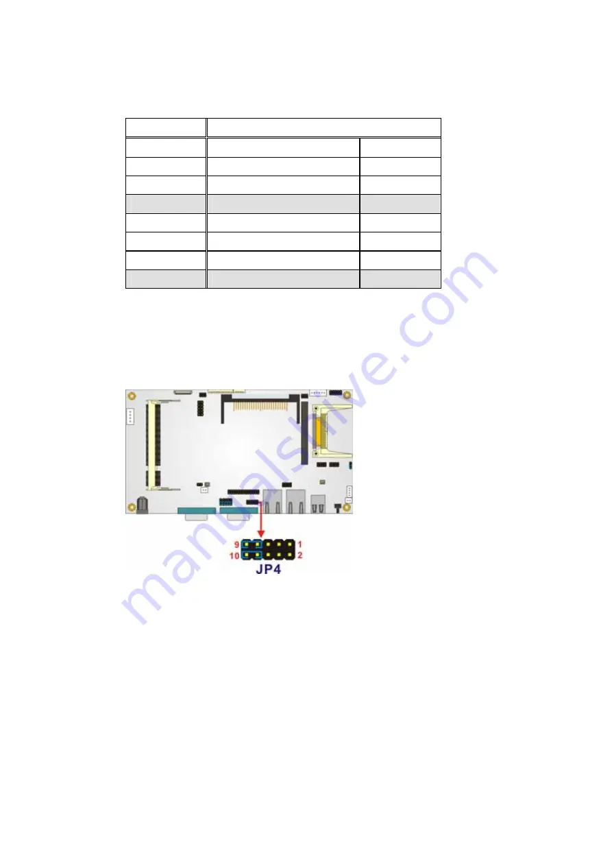
Table 3-6: COM1 and COM2 Pin-9 Signal Select Jumper Settings
The location of the COM1 and COM2 Pin-9 Signal Select jumper is shown in
Figure 3-5
below.
Figure 3-5: COM1 and COM2 Pin-9 Signal Select Jumper Location
3.7.4 COM2 Select Jumper Settings
Jumper Label:
JP5
and
JP6
Jumper Type:
12-pin header, 3-pin header
Jumper Settings:
See
Table 3-7
and
Table 3-8
Содержание EX-93821
Страница 1: ...Page 1 EX 93821 EX 93823 Flat Panel PC...
Страница 13: ...Page 13 1 Introduction Chapter 1...
Страница 27: ...Page 27 2 Motherboard Chapter 2...
Страница 35: ...Page 35 3 Installation and Configuration Chapter 3...
Страница 59: ...Page 59 4 Gasket Replacement Chapter 4...
Страница 61: ...Page 61 5 AMI BIOS Setup Chapter 5...
Страница 98: ...EX 93821 EX 93823 Flat Panel PC Page 98 3 3 V 12 V VBAT V 5VSB V...
Страница 99: ...Page 99 A Safety Precautions Appendix A...
Страница 103: ...Page 103 B BIOS Configuration Options Appendix B...
Страница 107: ...Page 107 C Software Drivers Appendix C...
Страница 116: ...EX 93821 EX 93823 Flat Panel PC Page 116 THIS PAGE IS INTENTIONALLY LEFT BLANK...
Страница 117: ...Page 117 D Hazardous Materials Disclosure Appendix D...
Страница 121: ...Page 121 E Index...


