background image

GTalarm3 User manual      V-2022-05-24 


23  | 

E N


3.4.2 

Fire alarm and Smoke sensors 

3.4.2.1 

Guidelines for Locating Smoke Detectors and CO Detectors  


The following information is for general guidance only and it is recommended that local fire codes and regulations be consulted when locating and installing 
smoke and carbon monoxide alarms. 
Smoke Detectors. Research indicates that all hostile fires in homes generate smoke to a greater or lesser extent. Detectable quantities of smoke precede 
detectable levels of heat in most cases. Smoke alarms should be installed outside of each sleeping area and on each level of the home. 
Additional  smoke  alarms  beyond those  required for minimum  protection  be  installed.  Additional  areas that  should  be  protected  include:  the  basement; 
bedrooms, especially where smokers sleep; dining rooms; furnace and utility rooms; and any hallways not protected by the required units. 
On smooth ceilings, detectors may be spaced 9.1m (30 feet) apart as a guide. Other spacing may be required depending on ceiling height, air movement, 
the presence of joists, uninsulated ceilings, etc.  
• Do not locate smoke detectors at the top of peaked or gabled ceilings; dead air space in these locations may prevent smoke detection. 
• Avoid areas with turbulent air flow, such as near doors, fans or windows. Rapid air movement around the detector may prevent smoke from entering the 
unit. 
• Do not locate detectors in areas of high humidity. 
• Do not locate detectors in areas where the temperature rises above 38

o

C (100

o

F) or falls below 5

o

C (41

o

F). 

Where required by applicable laws, codes, or standards for a specific type of occupancy, approved single- and multiple-station smoke alarms shall be 
installed as follows:  

(1) 

In all sleeping rooms and guest rooms. 

(2) 

Outside of each separate dwelling unit sleeping area, within 6.4 m (21 ft) of any door to a sleeping room, the distance measured along 

a path of travel. 

(3) On every level of a dwelling unit, including basements.  
(4) On every level of a residential board and care occupancy (small facility), including basements and excluding crawl spaces and unfinished attics. 
(5) In the living area(s) of a guest suite. 
(6) In the living area(s) of a residential board and care occupancy (small facility). 
CO Detectors.  Carbon monoxide gas moves  freely in the  air.  The human  body  is most  vulnerable to  the  effects  of  CO  gas  during sleeping  hours.  For 
maximum protection, a CO alarm should be located outside primary sleeping areas or on each level of your home. 
The electronic sensor detects carbon monoxide, measures the concentration and sounds a loud alarm before a potentially harmful level is reached. 
Do NOT place the CO alarm in the following areas: 
• Where the temperature may drop below -10ºC or exceed 40 ºC. 
• Near paint thinner fumes. 
• Within 5 feet (1.5 meters) of open flame appliances such as furnaces, stoves and fireplaces. 
• In exhaust streams from gas engines, vents, flues or chimneys. 
• In close proximity to an automobile exhaust pipe; this will damage the detector.


GTalarm3.  Begin the installation by mounting additional modules in the cabinet using the stand-offs provided, then mount the cabinet in a dry, protected 
area with access to un switched AC power. Install hardware in the sequence indicated in the following pages. Do NOT apply power until installation is 
complete. 


3.4.2.2 

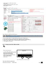
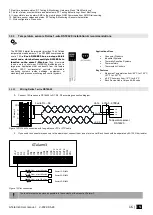
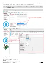
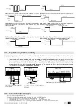
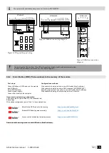
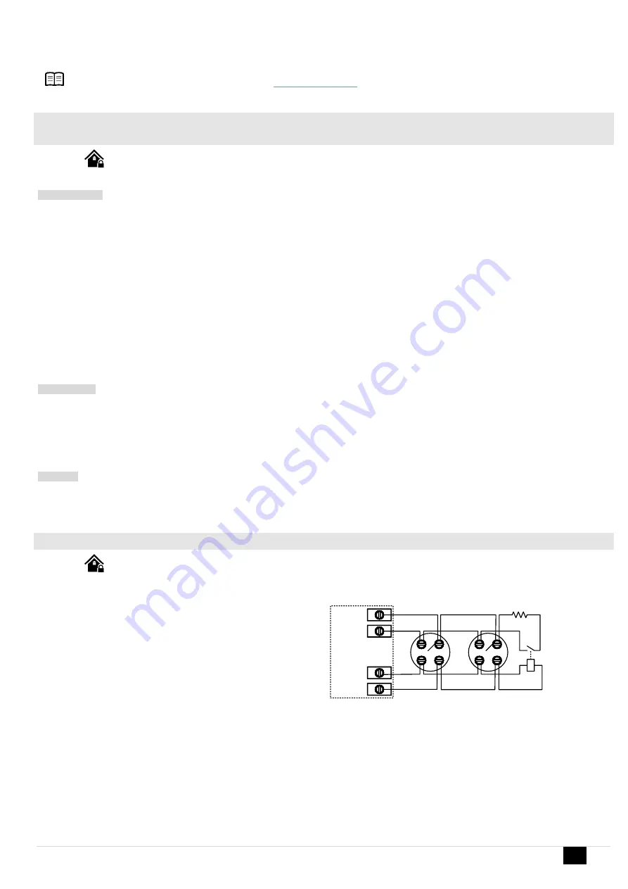
 [4-Wire] Smoke detector Wiring 


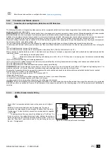
Connect the 4-wire smoke detectors and a relay as shown in the figure 
below.  
Install the 4-wire smoke detectors with 18 gauge wire. If power is 
interrupted, the relay causes the control panel to transmit the Fire Loop 
Trouble report. To reset (unlatch), connect the smoke detector’s negative 
(-) to a PGM.  

The parameters of the zone 

should be defined as a “Fire Zone”. If a 

line short occurs or the smoke detector activates, whether the system is 
armed or disarmed, the control panel will generate an alarm. If the line is 
open, the “Zone Fault” report code is sent to the monitoring station or to 
the user, if programmed. 


-


+


-


+


IN1...IN4

COM

OUT1...OUT4

+VD

Smoke 

detector

Smoke 

detector

NO

EOL

2.2k

G

Ta

la

rm

3


Figure 24 4-Wire Smoke Detector Installation 


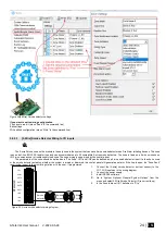
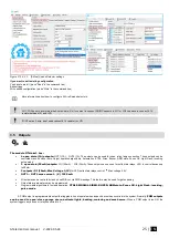
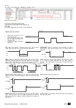
More information about how to configure the zones:

 Zones programming


Содержание GTalarm3

Страница 1: ...GTalarm3 Installation Programming Manual Security monitoring and automation system This manual includes steps to install set up and use your system...

Страница 2: ...d even growing tents Automation Remote control and monitoring various devices by GSM GPRS SMS DIAL WEB Internet FEATURES Report system events to a monitoring station Internet Protocol Event Reporting...

Страница 3: ...er iButton Probe Wiring 31 3 6 2 Enter iButton RFID Phone numbers to the memory of the module 32 3 7 How to set clock synchronization 33 5 Programming 35 5 1 SERA2 Uploading Downloading Software 35 5...

Страница 4: ...orage temperature range from 40 to 85 o C 40 to 185 o F Operational temperature range from 30 to 75 o C from 22 to 167 o F Max relative humidity under 40 o C 104 o F 95 Package weight 90g Module weigh...

Страница 5: ...or Is that it weakly pulls the voltage of the wire it is connected to towards V or whatever voltage represents a logic high PGM output A PGM output is a programmable output that toggles to its set up...

Страница 6: ...1 pcs User s guide in PDF Program SERA2 1 4 General view of the module 1 Micro SIM card holder of Push Push type 2 GSM antenna connector 3 RESET button 4 Mini USB programming connector 5 REG yellow se...

Страница 7: ...ects internally to COM Max available current 1000mA Max available voltage 30V 8 9 10 I O1 I O3 30 Programmable functions The zone for security system NC NO EOL EOL Tamper 1 Output 20mA Analog current...

Страница 8: ...rd via cloud app also in SERA remote default 123456 Installer code for SMS control and configuration 000000 INST000000 090 PSW 090 command code Change of installer s code PSW New Installer s password...

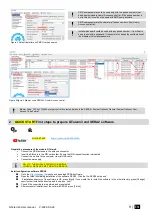
Страница 9: ...t 2 QUICK START First steps to prepare GTalarm3 and SERA2 software QUICK START https youtu be NR35lbFdi8A Preparation procedure of the module GTalarm3 Connect the GSM antenna to the antenna connector...

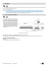
Страница 10: ...ply the security system from stabilized power supply source 10 15 V and not less than 1 5A It is necessary to calculate max current of power supply The current of the alarm system is the current used...

Страница 11: ...GTalarm3 User manual V 2022 05 24 11 E N Figure 6AC loss in Burglar alarm window...

Страница 12: ...y to follow all electrical safety requirements 3 2 Inputs The module GTalarm3 has 7 burglary zones Can be expanded up to 32 4 analog inputs In1 In4 0 30V for analog sensors connection Or can be used a...

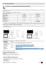
Страница 13: ...It would therefore seem that any particular device is not guaranteed to meet these specifications For all the other devices the numbers above are the maximum tolerances and most also offer better typ...

Страница 14: ...onitoring 9 It is possible to receive alarm SMS to the mobile phone GSM Communication SMS Dial reporting 10 Real time sensor values and states RT Testing Monitoring Sensors Automation 11 Write configu...

Страница 15: ...Set the required parameters 4 Sensors could be calibrated 5 Press Write Figure 11Analog sensors settings Any automation voltage analog sensors 0 10V can be connected to IN1 IN4 has internal pull up re...

Страница 16: ...temperature monitoring systems inside buildings equipment or machinery and process monitoring and control systems Applications Uses Consumer Products Industrial Systems Thermally Sensitive Systems The...

Страница 17: ...istor in series in the data line of each sensor before connecting to the network The total length of the bus from 10 to 100m Depending of cable quality sensors number on bus and environment noise Ther...

Страница 18: ...ime hardware status RT Testing Monitoring Hardware Press Start Monitoring 8 The list of alarm events with time and date stamp RT Testing Monitoring Event Monitoring 9 It is possible to receive alarm S...

Страница 19: ...step How to check real time hardware status real time sensor values How to receive alarms and where find alarm events list 7 Real time hardware status RT Testing Monitoring Hardware Press Start Monito...

Страница 20: ...zones with selectable type NC NO EOL EOL TAMPER I O1 I O2 with selectable type NC NO EOL EOL TAMPER External pool up resistor 5 1K is required It is recommended to use standard motion fire and glass...

Страница 21: ...OUT4 OUT3 I O1 IN4 IN3 IN2 D3 OUT1 5V OUT2 D1 D2 VD COM IN1 I O2 GTalarm3 Figure 19 NO With EOL COM NC TAMPER NO COM NC ALARM RELAY OUTPUT sensor EOL cable EOL zone input com 2 2k 2 2k tamper switch N...

Страница 22: ...or I O2 you have to connect external 5 1K resistor between I O and VD as is shown in attached diagram I O1 I O2 do not have internal pull up resistors So if you want to connect NO NC sensors to I O1...

Страница 23: ...ery level of a residential board and care occupancy small facility including basements and excluding crawl spaces and unfinished attics 5 In the living area s of a guest suite 6 In the living area s o...

Страница 24: ...ng is supervised by the control panel The parameters of the zone should be defined as a Fire Zone I O1 and I O2 can be defined as a 2 wire smoke detector input if a line short occurs or the smoke dete...

Страница 25: ...ration algorithms Automation CTRL Siren Buzzer ARM state Zones OK Light Flash inverting pulse mode 3 open drain 20mA outputs I O1 20mA I O3 20mA These outputs can be used for solid state relays LED to...

Страница 26: ...pulse signal is generated within Exit Delay time and continuous signal within Entry Delay time or when the alarm system is disturbed When the alarm system is turned off operates like keyboard buzzer O...

Страница 27: ...ve terminal to the selected output 1 Connect devices to the selected outputs as shown in the figures below For sound signaling we recommend to use siren DC 12V up to 1500mA It is recommended to connec...

Страница 28: ...mode In order to control big power alternating current equipment it is comfortable to use solid state relays Standard AC DC adapter with the voltage 10V 14V and current 1A might be used to powering th...

Страница 29: ...text to the system s phone number USER 123456 030 ST 030 command code Change security system s mode ARM DISARM STAY SLEEP ST Security system mode 0 DISARM 1 ARM 2 STAY 3 SLEEP Arm Disarm by keypad To...

Страница 30: ...r will call from this number Preferred input may be assigned to each user s number Thus different users are able to control different objects ARM DISARM If this check box is checked a user will be abl...

Страница 31: ...s of a week They are similar but of higher rank than the standard Monday Sunday If a day programmed as a Holiday should occur in the panel the panel will treat that day as the Holiday type regardless...

Страница 32: ...to the memory of the module First steps Connect iButtons or RFID reader to the module Insert SIM card Screw GSM antenna Connect power supply Connect the module to the computer Configurations methods...

Страница 33: ...iButton RFID Caller ID Learning Mode Stopped INST000000 063 S INST Install Configuration of the parameters 000000 Installer s password Space character 063 command code iButton keys learning deleting m...

Страница 34: ...ire Bus must be set Refer to Users Access Control programming details 3 7 How to set clock synchronization If you received SMS messages with wrong date time you need to set clock synchronization corre...

Страница 35: ...iguration press Write in the command line Figure 40 SERA2 Command line 4 Programming In order to configure and control the system by SMS text message send the text command to the GTalarm3 phone number...

Страница 36: ...ings may be saved at PC It enables to save time when next time the same configuration will be used it will not be necessary again to set the same parameters If you want to save that is already recorde...

Страница 37: ...rrect date and time otherwise the system will not operate properly SERA2 software provides the ability to select the Time Zone and The user may also choose Set module time from PC which instantly prov...

Страница 38: ...armed disarmed or that an Entry or Exit Delay was triggered Auto reARM Arm the module if there is no activity in the area after the system disarming Stop iButton RFID programming To finish entering iB...

Страница 39: ...and voltage is dropped below allowed value Event Delay System low voltage trouble event report delay Audible alarm when disarmed alarm as per zone when armed When disarmed Generates Audible Alarm The...

Страница 40: ...can be expanded GTalarm3 zones can be expanded with expansion module up to 32 Zone bypassing allows the user to deactivate a violated zone and arm the system without restoring the zone If a bypassed...

Страница 41: ...t be disabled The tamper circuit is a single closed loop such that a break in the loop at any point will cause a tamper alarm regardless of the system status armed or disarmed During the tamper alarm...

Страница 42: ...t a tamper condition with one or more sensors on the system Bypass Enabled The system will allow zones to be Manually Bypassed Shutdown if max alarm count The system will stop generating alarms once t...

Страница 43: ...ection of electrical devices which will be controlled by SMS message or phone call Ready Output for connection of light indicator of input statuses If all zones are clear none violated a continuous si...

Страница 44: ...nal code iButton Code iButton key DS1990A 64 Bit ID code Might be entered manually or automatically registered after the module enters keys association mode In order to delete the code it is necessary...

Страница 45: ...ng Crew schedule The schedules are to be set up as follows Monday Friday 5 p m 1 a m Saturday and Sunday 8 a m 1 p m no holidays This becomes three separate schedules as follows 2 Monday Friday 5 p m...

Страница 46: ...d in one of four modes DISARM ARM SLEEP STAY By default it is allowed to arm the system while the following system faults are present Low battery Battery dead or missing Battery failed Date time not s...

Страница 47: ...smits the defined report code and generates an audible alarm When armed Follows Zone Alarm Type The module follows the zone s alarm type Trouble always Generates Trouble Only when armed or disarmed Tr...

Страница 48: ...rough 8 for monitoring purpose receive alarm phone calls via GSM connection and SMS text messages from the system When the system is armed or disarmed by free of charge phone call or SMS text message...

Страница 49: ...the next listed user phone number assigned to the same zone The user can be unavailable due to the following reasons Mobile phone was switched off mobile phone was out of GSM signal coverage or provi...

Страница 50: ...xt SMS Text Text which will be visible in SMS message is entered Alarm SMS message text of Alarm report Restore SMS message text of Restore report Open SMS message text of Open report Close SMS messag...

Страница 51: ...during the remote connection session process the data messages will be queued up and transmitted to the monitoring station after the remote connection session is over while during the remote firmware...

Страница 52: ...station CMS is disable switch to backup CMS after n attempts 9 Return To Primary After n min Return To Primary After n min 10 Encryption AES128 The Encryption option validates the encryption of messa...

Страница 53: ...Numerical Report Options 1 1 RT Testing Monitoring Hardware RT Testing Monitoring Hardware The Hardware monitoring window let you see real time input output actions and GSM information Thus it would b...

Страница 54: ...appropriate output Out1 Out4 means that this output currently has 0 or 1 state The output could be activated by pressing On Off button 28 29 I O1 I O2 On Off Checked box nearby the appropriate input...

Страница 55: ...implest application viewing data to more sophisticated uses such as sending a text message when an alarm occurs or transmitting a data log file over the internet from a remote location to a central of...

Страница 56: ...red Read icon 5 The connected sensors will appear in the list Figure 54 the example of Automation Sensors Automation Sensors Analog Inputs window How to set sensor s parameters Double click on the sel...

Страница 57: ...Unit Sensor Unit Text 6 Max Value Alarm Event SMS Max Val SMS Maximum allowable temperature value which will be reported 7 Max Value To Activate Output Max Val OUT Maximum allowable temperature value...

Страница 58: ...least Temperature X ADC Y 12 Contact ID Report Code Max CID Max and Min Contact ID report codes Report codes are the Ademco CID SIA DC09 format The module can automatically program a set of default r...

Страница 59: ...tion by MIN and MAX boundaries System faults Configuration via USB User phone number that initiated the remote configuration Communication with monitoring station status Figure 58 the example of the E...

Страница 60: ...to GSM Communication window Sera Cloud Service tab Set Sera Cloud Service to Default parameters 5 Write the configuration into the module by pressing Write icon Figure 59 How to find GSM Communicatio...

Страница 61: ...ected notification SERA2 software can remember all IMEI that was entered in the past If needed to clean the list UID IMEI press Clear History Figure 61 Command line Settings Clear history 4 17 Testing...

Страница 62: ...green the sensor is active 4 High Val Alarm If checked and the color is red the high value alarm is generated 5 Low Val Alarm If checked and the color is red the low value alarm is generated 4 17 2 Re...

Страница 63: ...No Updates System Options System Info The System Info window let you take a look to the main hardware boot loader firmware serial no IMEI ICCID information 1 2 3 4 5 Figure 65 How to find required Sy...

Страница 64: ...s the problem with sensor s connection to the module If the problem still exist please read save and send the configuration to the seller Describe what and how is connected to zone 001 and send this i...

Страница 65: ...SMS event filter for sms 1 send event 0 don t send event Sequence of the events 1 2 3 n For example 001000 DIAL event filter for DIAL 1 DIAL if the event occur 0 don t DIAL Sequence of the events 1 2...

Страница 66: ...anel 12 Lost secondary chanel 13 Fire sensor14 RH Sensor trouble 15 Access Gained INST000000 020 N Invert output state 020 command code outputs inversion N output number from 1 to 10 INST000000 021 N...

Страница 67: ...1 31 HH hours 0 23 mm minutes 0 59 INST000000 094 TEL SMS SMS from the module forwarding to the other phone number SMS from the module forwarding to the other phone number 094 command code SMS from t...

Страница 68: ...99 Time interval in seconds for the output activation USER123456 030 ST Change security system s mode ARM DISARM STAY SLEEP 030 command code Change security system s mode ARM DISARM STAY SLEEP ST Secu...

Страница 69: ...OT install the module near water e g bathtub wash bowl kitchen laundry sink wet basement or near a swimming pool Do NOT install the module and its accessories in areas where there is a risk of explosi...

Страница 70: ...on purporting to act on its behalf to modify or to change this warranty nor to assume for it any other warranty or liability concerning this product WARNING UAB Topkodas recommends that the entire sys...

Страница 71: ...any other part of the detection system will impair its proper operation Passive infrared motion detectors operate by sensing changes in temperature However their effectiveness can be reduced when the...

Отзывы: