Topcon MR-2 Скачать руководство пользователя страница 17

Cables and Accessories  

 8 

P/N: 1011907-01

Get

ting Acquai

nt
ed

Receiver Accessories

The MR-2 has a variety of accessories to increase its ease of use and facilitate installation. Table 2 lists these 

accessories. For more details on the optional accessories available for the MR-2, contact a local Topcon dealer.

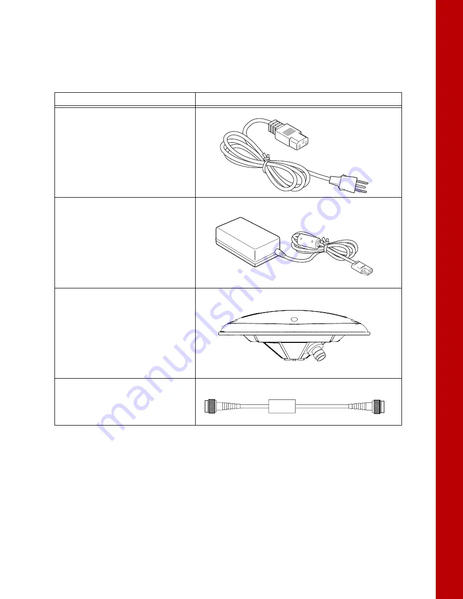
Table 2. MR-2 Package Cables

Cable Description

Cable Illustration

Cable, Power/Charger

Connects the power supply unit to a 
grounded outlet.
p/n 14-008052-01 (US)
p/n 14-008053-01 (AUS)
p/n 14-008054-01 (EUR)

Power Supply Unit

Converts the alternating current (AC) 
supplied from an electrical outlet to a direct 
current (DC) for powering the receiver. 
The unit connects to the receiver via the 
power adapter cable.
p/n 22-034101-01

Full Wave Antenna

For optimal performance, the MR-2 should be 
paired with a high precision Topcon GNSS 
antenna. The PG-F1 offers high performance 
signal tracking for full constellation operation, 
while the PG-S1 may be used for dual 
frequency configurations.

Cable, External Antenna

Connects the external antenna to the 
receiver.

Содержание MR-2

Страница 1: ...MR 2 GNSS Receiver Operator s Manual ...

Страница 2: ...uary 2017 All contents in this manual are copyrighted by Topcon Positioning Systems Inc All rights reserved For more information contact Synergy Positioning Systems or visit the Synergy Positioning Systems website at www synergypositioning co nz All branches Phone 0800 867 266 Email info synergypositioning co nz ...

Страница 3: ... Introduction 1 Receiver Features 1 Unpacking the Receiver 2 Getting Technical Support 2 Website 3 Getting Acquainted 4 Communication and Power Port 4 Power Input 4 Com Features 4 PPS Connector 4 Ethernet Connector 4 Antenna Connectors 5 Option Authorization File OAF 6 Twin Antenna System HD2 6 Cables and Accessories 7 Standard Cables 7 Receiver Accessories 8 Mounting the Receiver 9 LED Indicators...

Страница 4: ...nal 17 Install the Topcon Receiver Utility TRU 18 Managing Power 19 Turning the Receiver On Off 19 Powering the Receiver 19 Connect to an External Power Source 19 Power Cycling 19 Configuration 20 Connect The Receiver to TRU 20 Ethernet Connection 22 Receiver Ethernet Settings 22 View Receiver IP Addresses 22 Set Up a Static IP Address For the Laptop 23 View Receiver Password 24 Change Password 24...

Страница 5: ...eshooting 53 Check This First 53 Powering Problems 53 Receiver Problems 53 Clear NVRAM Using TRU 55 Cleaning and Storing the Receiver 55 Safety Warnings 56 General Warnings 56 Receiver Warnings 56 Usage Warnings 56 Specifications 57 General Details 57 Connector Specifications 60 Main Connector 60 Ethernet Connector 61 Cable Harness 62 Cable Harness Receiver End Connector 62 Cable Harness Power Con...

Страница 6: ...Table of Contents v P N 1011907 01 Table of Contents European Community Declaration of Conformity 69 Declaration of Conformity R TTE Directive 1999 5 EC 69 WEEE Directive 70 Warranty 71 Glossary 72 ...

Страница 7: ...ure of considerable work time and money and are the result of original selection coordination and arrangement by TPS Trademarks MR 2 TRU HD2 Topcon and Topcon Positioning Systems are trademarks or registered trademarks of TPS Windows is a registered trademark of Microsoft Corporation Other product and company names mentioned herein may be trademarks of their respective owners Disclaimer of Warrant...

Страница 8: ...ial and proprietary information of TPS You agree to treat TPS Confidential Information with a degree of care no less stringent that the degree of care you would use in safeguarding your own most valuable trade secrets Nothing in this paragraph shall restrict you from disclosing Confidential Information to your employees as may be necessary or appropriate to operate or care for the Product Such emp...

Страница 9: ...Finish Mono User supplied text or variable Type guest and click Enter Italic Reference to another manual or help document Refer to the Topcon Reference Manual Further information to note about system configuration maintenance or setup Supplementary information that can have an adverse affect on system operation system performance data integrity measurements or personal safety Notification that an ...

Страница 10: ...con communication interface allows you to quickly integrate Topcon s premium GNSS performance within new systems and quickly deliver world class positioning and navigation support to your applications The MR 2 features include Vanguard technology for future proof tracking of GPS GLONASS Galileo BeiDou and QZSS satellite signals 226 universal tracking channels Proven Topcon GNSS technology delivers...

Страница 11: ...e contacting a Topcon customer representative see Troubleshooting on page 53 for some solutions that may fix issues you might have with the receiver Contact your local Topcon dealer or visit the myTopcon website at https www topconpositioning com support for technical support When contacting Topcon for technical assistance provide the following information 1 A description of the following Field op...

Страница 12: ...cess to Topcon field and office software manuals frequently asked questions and so forth To access the Topcon website visit http www topconpositioning com The myTopcon website also provides complete support such as news updates reminders training live webinars product registration and customer service to help you get the information you need Visit https www topconpositioning com support ...

Страница 13: ...2C level signals Supports baud rates of 115 200 and higher Supports RS232 RX and TX signals Supports simultaneous output of position and status data along with input of control commands and or differential corrections for RTK Supports CAN Supports GNSS board firmware upgrades Supports input of differential RTK corrections from an external radio source PPS Connector Modern synchronization and time ...

Страница 14: ...ion For more information see Step 4 Connect Dual Antennas HD2 on page 14 For complete MR 2 operation the external antenna supports at least GPS L1C A L2C L2P Y GLONASS L1 L2 and SBAS WASS MSAS EGNOS signal tracking and accept voltage at 4 75 to 5 10 VDC at 0 70 mA Topcon guarantees performance specifications of the MR 2 only when used with Topcon antennas such as PG F1 GNSS antennas Figure 2 MR 2 ...

Страница 15: ...M or resetting the receiver The OAF enables the following kinds of functions Signal tracking standard L1 GPS optional L2 signal tracking Update rate standard 1Hz optional 5 10 20 50 or 100 Hz RTK at 1 5 10 20 50 and 100 Hz RTCM CMR Input Output 2 D attitude determination Advanced multipath reduction Satellite Based Augmentation System positioning WAAS EGNOS MSAS RS 232C 2x connectivity Twin Antenn...

Страница 16: ...9 connectors Connects the receiver to external devices controller or computer for data transfer and receiver configuration BNC connector Provides accurate time transfer to external devices p n 14 008207 02LF Power Adapter Converts the Deutsch 3 pin connector to an SAE connector for connection to a 9 36 VDC power supply p n 1000231 01 Ethernet Cable SAE connector Connects the receiver to a 9 36 VDC...

Страница 17: ...o a grounded outlet p n 14 008052 01 US p n 14 008053 01 AUS p n 14 008054 01 EUR Power Supply Unit Converts the alternating current AC supplied from an electrical outlet to a direct current DC for powering the receiver The unit connects to the receiver via the power adapter cable p n 22 034101 01 Full Wave Antenna For optimal performance the MR 2 should be paired with a high precision Topcon GNSS...

Страница 18: ...ou to easily secure the receiver in any orientation onto any hard surface with the strength to withstand tough environmental conditions Figure 3 Figure 3 MR 2 Mounting Dimensions 29 1 14 80 3 15 153 7 6 05 165 9 6 53 128 8 5 07 11 7 0 46 152 5 98 163 1 6 42 136 4 5 37 7 Dia 28 4 PLCS 8 5 0 33 48 5 1 91 134 4 5 29 136 4 5 37 171 7 6 76 ...

Страница 19: ...ity and tracked satellites This section describes the color and behavior of each LED Power LED The Power LED indicates whether the receiver is on or off and to indicate the status and type of OAF loaded Power Ethernet STAT Primary Antenna STAT Secondary Antenna Table 3 Power LED Patterns LED Color Description When the LED is off the receiver is off When the LED is blinking or solid the receiver is...

Страница 20: ...es the number of satellites for that constellation Table 5 describes the blink patterns Table 4 Ethernet LED Patterns Display Description Solid Red No Ethernet connection Solid Green Ethernet Connection established Table 5 STAT LED Blink Order Definition 1 Green blink per tracked GPS satellite 2 Dark once 3 Yellow blink per tracked GLONASS satellite 4 Dark once 5 Cyan blink per tracked Galileo sat...

Страница 21: ...to both ports at the same time The receiver draws power from the port with the higher voltage If both voltages are the same power will passively switch between both ports The switching happens within operating range and causes no drop in power The receiver will work without interruption 1 Mount the receiver to a suitable hard surface where the LED is visible and the ports are accessible See also M...

Страница 22: ...ector on the cable harness to the serial port on the computer or display 2 Optional If the MR 2 is RTK enabled connect the COM2 serial port connector to the serial port of the RTK correction source Figure 8 Cable Harness COM1 and COM2 Serial Ports Step 3 Connect a Single Antenna To connect a single external antenna for precise positioning 1 Mount the GNSS antenna on a rigid surface 2 Connect the a...

Страница 23: ... antenna cable to the front antenna and the secondary antenna connector of the MR 2 4 Enable HD2 moving base corrections at the primary antenna and HD2 heading determination at the secondary antenna See the B125 Integrator s Guide for more information Step 5 Connect to a PPS Signal 1 Connect the PPS connector on the cable harness to a PPS input port of a suitable instrument 2 Configure the PPS out...

Страница 24: ...s as shown in Figure 11 Figure 11 Power Adapter Cable to the Power Connector 3 Connect the other end SAE connector of the power adapter cable to a 9 36 VDC power supply unit with an SAE connector as shown in Figure 12 Figure 12 Power Adapter Cable to Power Supply Unit 4 Verify the power supply is on and supplying power 5 Make sure the MR 2 LED is lit solid which indicates it is receiving power You...

Страница 25: ...able Connections 1 Connect the Ethernet cable to the MR 2 2 Connect the RJ45 end of the Ethernet cable to a source 3 Connect the SAE end of the Ethernet cable to a power source Step 3 Connect a Single Antenna To connect a single external antenna for precise positioning 1 Mount the GNSS antenna on a rigid surface 2 Connect the antenna cable to the primary antenna connector circled in red in Figure ...

Страница 26: ... antenna cable to the front antenna and the secondary antenna connector of the MR 2 4 Enable HD2 moving base corrections at the primary antenna and HD2 heading determination at the secondary antenna See the B125 Integrator s Guide for more information Step 5 Connect to a PPS Signal 1 Connect the PPS connector on the cable harness to a PPS input port of a suitable instrument 2 Configure the PPS out...

Страница 27: ...ta 7 operating system an RS 232C port or an Ethernet port Mobile editions are also available for Topcon supported devices equipped with serial connections running WinCE 5 WinCE 6 WinMobile 6 1 6 5 6 5 3 To install and run TRU on a computer 1 Visit myTopcon https www topconpositioning com support and download the file 2 Locate the TRU exe file on your computer and double click the file to run the i...

Страница 28: ... begin the startup process lasting approximately 1 to 1 5 minutes Some receiver functions may be available during this process All functions of the receiver are available when the startup process completes Powering the Receiver The receiver is powered by an external power source connected to either the serial connector or Ethernet connector Connect to an External Power Source To power the receiver...

Страница 29: ...shed you can Set up GPS parameters and other settings Monitor the receiver s GPS status Log raw data to a file Load a new OAF firmware and other configuration files to the receiver Connect The Receiver to TRU The steps in this section work with receivers that have one or two boards 1 Connect the receiver and computer as described in Step 2 Connect to a Computer or Display Unit and RTK Correction S...

Страница 30: ...he right of Port Name 7 Choose a port from the Select Port screen and click OK Figure 19 The Connection Parameters screen appears Figure 19 TRU Select Port Screen The Port Name shows the friendly and physical name of the computer port The application remembers the last used transport and the last used successful port device name for every transport making it easy to connect to the same device ...

Страница 31: ...r laptop For a laptop connection set up a static IP address on the computer Once connected the Ethernet LED will be solid 2 5 seconds after the receiver is powered on indicating that an Ethernet connection is established If the Ethernet LED does not become green after 10 seconds check the external network connect or reboot the receiver View Receiver IP Addresses The receiver contains a main and au...

Страница 32: ... receiver s IP address is 10 5 57 200 the computer IP address must be 10 5 57 xxx 1 Open the Network and Sharing Center on your laptop 2 Change your Local Area Connection TCP IPv4 settings to match the receiver Figure 21 Figure 21 Laptop Internet Protocol Settings 3 Enter the IP address for the primary board see View Receiver IP Addresses on page 22 4 If needed enter the Default gateway address 5 ...

Страница 33: ...e 22 3 Click the TCP tab and enter a new password in the Password field 4 Click OK and reset the receiver to enable the new password Reset the Receiver After changing Ethernet settings reset the receiver Open the Terminal window enter set reset yes and click Send The IP addresses become assigned within 30 seconds after reset The Receiver will reply with a ping and become accessible by TCP ports fr...

Страница 34: ...er The TRU main screen displays Figure 17 on page 20 Initially the tools are inactive 2 Click Device Application Mode Receiver Managing 3 Click Device Connect The Connection Parameters screen appears 4 Select Network from the Connect Using drop down list Figure 23 Figure 23 TRU Connection Parameters Network ...

Страница 35: ...transport and the last used successful port device name for every transport making it easy to connect to the same device 6 If needed right click on the desired port and click Edit The Network Connection Parameters screen appears Figure 25 Figure 25 Network Connection Parameters 7 Enter the IP address and password of the GNSS receiver you want to connect to The main board IP address is 192 168 0 9 ...

Страница 36: ...ng describes how to configure the receiver as a base Configure the Antenna 1 In TRU click Device Application Mode Receiver Managing Receiver Settings The Receiver Settings screen appears Figure 26 Figure 26 TRU Receiver Settings 2 Click Tracking Positioning The Tracking Positioning screen appears Figure 27 on page 28 3 Click the Antenna tab and set the GNSS Antenna type to External Do not make oth...

Страница 37: ...e 4 Click the Obs tab and set the following parameters Figure 28 Elevation Mask deg Set Satellites Tracking to 5 degrees Elevation Mask deg Set Position Computation to 13 degrees PDOP Mask Set Position Computation to 30 degrees Figure 28 Configure Receiver Positioning Elevation Mask ...

Страница 38: ...e Cinderella check box is unselected Only select this option if you want to set all of the receiver options to their maximum allowable values for 24 hours every other Tuesday at GPS midnight Figure 29 Configure Advanced Parameters 6 Click OK to return to the Receiver Settings screen 7 Configure the reference coordinates by entering them using GRIL commands see Commands of the GRIL Reference Guide ...

Страница 39: ...ngs screen appears Figure 31 Figure 31 TRU Receiver Settings 2 Click Ports The Receiver Ports screen appears Figure 32 on page 30 3 Double click the appropriate Serial Port name Figure 33 on page 31 The Settings screen for that port appears Figure 32 TRU Receiver Ports 4 In the Settings screen select the following Figure 33 Input Mode Select Command Output Mode Select RTK RTCM 3 1 ...

Страница 40: ...eiver Settings screen then click Back to return to the TRU main screen Set Up The Receiver TCP Port 1 In TRU click Device Application Mode Receiver Managing Receiver Settings The Receiver Settings screen appears Figure 34 Figure 34 TRU Receiver Settings 2 Click Ports then click the TCP tab The Receiver Ports screen for the TCP tab appears Figure 35 3 Double click the appropriate TCP Port name Figu...

Страница 41: ...eceiver 32 P N 1011907 01 Configuration Figure 35 TRU Receiver TCP Port 4 In the Settings screen select the following Figure 36 Input Mode Select Command Output Mode Select RTK RTCM 3 1 Figure 36 TRU TCP Port Settings ...

Страница 42: ...n then click Back to return to the TRU main screen Set Up Additional Messages Optional 1 In the Settings screen for your selected serial port click Messages The Messages screen appears Figure 37 on page 33 Figure 37 TRU Serial Port Messages 2 Right click in the screen and click Add new messages The Receiver Message List screen appears Figure 38 on page 34 Disabling authentication or changing the p...

Страница 43: ...ick the message to add it The message appears in the bottom list panel Figure 39 Figure 39 New Serial Port Message Added If you want to edit the new message follow the procedure below Otherwise Click OK to return to the Settings screen Click OK again to return to the Receiver Ports screen and Click X to return to the Receiver Settings screen Finally click Back to return to the TRU main screen ...

Страница 44: ...urn to the Messages screen then click OK again to return to the Settings screen 5 In the Settings screen click OK to return to the Receiver Ports screen then click X to return to the Receiver Settings screen 6 Click Back to return to the TRU main screen Configure the Receiver as a Rover The following describes how to configure the receiver as a rover Set the Receiver Positioning 1 Follow steps 1 6...

Страница 45: ...o ranges RTK Float Where the Rover receiver computes the current relative coordinates in differential mode using both pseudo ranges and phases however with a float solution the phase ambiguity is not a fixed integer number and the float estimate is used instead RTK Fixed Where the rover receiver computes current relative coordinates with ambiguity fixing in differential mode DION Select the mode i...

Страница 46: ...ver Settings 2 Double click the appropriate Serial Port name Figure 42 The Settings screen for that port appears 3 In the Settings screen select the following Figure 43 Input Mode Select RTCM 3 x Output Mode None Figure 43 Serial Port Settings 4 Click OK to return to the Receiver Ports screen then click X to return to the Receiver Settings screen 5 Click Back to return to the TRU main screen ...

Страница 47: ...n click the TCP tab Figure 44 The Receiver Ports screen for the TCP tab appears Figure 44 Receiver Settings 2 Double click the appropriate TCP Port name Figure 45 The Settings screen for that port appears 3 In the Settings screen select the following Figure 45 Input Mode Select RTCM 3 x Output Mode None Figure 45 Serial Port Settings ...

Страница 48: ...figured the configuration remains until changed using TRU or by clearing the NVRAM For more details on the settings available for configuring receivers see the TRU Online Help embedded in the software Verify Receipt of Differential Corrections RTK Rover Only 1 For RTK Rover receivers click Status Figure 46 to ensure the receiver obtains differential correction The Status screen appears Figure 46 T...

Страница 49: ...e port is not configured or if the corrections are not being received the Link Quality field will be empty Figure 47 Status Data Link 2 When finished click X to close the Status screen and return to the TRU main screen 3 Click Device Disconnect then Device Exit to close TRU Disconnecting before exiting TRU ensures proper port management ...

Страница 50: ... moving base will process its position with centimeter level accuracy using the measurements from the stationary base station It will then transmit the position to the rover HD2 operation requires scripts that will configure the receiver by sending commands to the master board of the MR 2 Several scripts are available on the Topcon Positioning Systems website which cover the popular work flows of ...

Страница 51: ... secondary board Check the Receiver s OAF Use TRU to view the status of the receiver s options 1 Connect the receiver to a computer See Step 2 Connect to a Computer or Display Unit and RTK Correction Source on page 13 2 Open TRU and connect to the receiver See Connect The Receiver to TRU on page 20 3 Click the Options icon in the main screen The Receiver Options screen displays so you can view the...

Страница 52: ...iver s ID and serial number To obtain these numbers see Check the Receiver s OAF on page 42 1 Follow the steps in Check the Receiver s OAF on page 42 2 Right click in the Receiver Options screen and select Upload OAF Figure 50 Figure 50 Right click and Select Upload OAF 3 Navigate to the location of the new Option Authorization File 4 Select the appropriate file and click Open Figure 51 Figure 51 ...

Страница 53: ...receiver the Upload OAF window displays an error icon next to the Receiver ID and disables the Upload the File to the Receiver button 5 Click Upload the File to the Receiver to start loading the file Figure 52 Figure 52 Upload the OAF to the Receiver 6 Click Yes at the prompt to reset the receiver Figure 53 Figure 53 Reset Receiver When the receiver resets the Connection Parameters screen opens ...

Страница 54: ...OAF 45 P N 1011907 01 Configuration 7 Click Connect Figure 54 The TRU main screen appears Figure 54 Connect to the Receiver 8 Click Options Figure 55 The Receiver Options screen displays Figure 55 Click Options ...

Страница 55: ...If you upload a universal OAF make sure the expiration date is still valid If you upload a customer OAF make sure the correct customer file is loaded Figure 56 Receiver Options 10 To view additional OAF details right click in the Receiver Options screen and select View Detailed Figure 57 Figure 57 Additional OAF Details ...

Страница 56: ... Configuration The Receiver Options screen switches to a detailed view with additional information Figure 58 Figure 58 Receiver Options Detailed View 11 Click X to close the Receiver Options screen and return to the TRU main screen ...

Страница 57: ...auxiliary board is 192 168 0 10 Follow the below procedure for both boards 1 Download the latest firmware build to your PC 2 Open TRU and click Device Application Mode Receiver Managing 3 Connect to the receiver using an Ethernet connection Figure 59 Figure 59 TRU Ethernet Connection 4 Click Connect 5 Once connected click Device Application Mode Firmware Loading Do not unplug the power or Ethernet...

Страница 58: ...reen appears Figure 60 Figure 60 TRU Firmware Loading 7 Select Receiver from the Device Type drop down list 8 Click Next The Information screen appears Figure 61 Figure 61 TRU Receiver Information 9 Verify that the information is correct and click Next The Select Files screen appears Figure 62 on page 50 ...

Страница 59: ...o and select the firmware build you downloaded in step 1 Figure 62 Locate and Select Firmware 11 Click Next to the begin the upload Once the begins a status screen appears Figure 63 Do not unplug the power or Ethernet connection during this process Figure 63 Firmware Upload In Progress ...

Страница 60: ...ow in TRU 16 Enter print dev core on and click Send During the update process the receiver will return the following RE00F par dev core RE01B 0 mode normal state run RE01F 1 mode update state updateX When the update process is finished the receiver will return the following RE00F par dev core RE01B 0 mode normal state run RE01B 1 mode normal state run 17 Repeat steps 2 16 for the auxiliary board 1...

Страница 61: ...al radio The primary antenna connection enables you to connect an external survey grade antenna and use the receiver as a rover suited to the job requirements Site Reference Station You can integrate the MR 2 with an external radio using serial communication and use it as a base receiver As a base the MR 2 configuration can output RTK corrections in industry standard format for a rover receiver to...

Страница 62: ...nd undamaged Make sure the power source is not defective Using a volt meter ensure power is present to the power source output connector Power cycle the receiver See Power Cycling on page 19 for more information Receiver Problems The following are some of the most commonly encountered receiver problems The receiver cannot establish a connection to a computer or external controller Cable specific p...

Страница 63: ...abled or expired Order a new OAF with the required options activated to enable or extend validity of the corresponding receiver options Contact a dealer or visit the TPS website for details Refer to the TRU Online Help embedded in the software There are not enough common satellites In order to obtain a fixed solution the Base and Rover should track at least five common satellites Check the elevati...

Страница 64: ...latile Random Access Memory NVRAM holds data required for satellite tracking such as ephemeris data and receiver position The NVRAM also keeps the current receiver s settings such as active antenna input elevation masks and recording interval Even though clearing the NVRAM is not a common nor normally a recommended operation there are times when clearing the NVRAM can eliminate communication or tr...

Страница 65: ... at the survey site Contrary to applicable laws rules and regulations Tampering with the receiver by the end users or non factory authorized technicians will void the receiver s warranty Do not attempt to open the receiver and modify any of its internal components Do not charge in conditions different than specified Do not short circuit If this product has been dropped altered transported or shipp...

Страница 66: ...ileo E1 E5a E5b E5AltBoc Compass B1 B2 SBAS Corrections WAAS EGNOS MSAS QZSS Nav L1 C A L1C L2C L5C L band Yes 1525 1560 MHz Antenna Type External Supports dual antenna input for heading determination through Topcon HD2 technology Multipath Reduction Yes code and carrier PLL DLL Setting Adjustable bandwidth and order Smoothing Interval Adjustable code and carrier Data and Memory Internal Memory Up...

Страница 67: ...atts 9 36 VDC typical Dual 8 watts 9 36 VDC typical 12 watts max Power and Communications Ports Deutsch DTM Series 12 pin Receptacle for power and communications Serial x3 CAN and PPS on main connector Turck M12 8 Pin Breaks out to RJ45 and SAE power Antenna Connectors 2x TNC Antenna power 4 75 5 10 VDC LEDs 4 LEDs Power Ethernet Primary Antenna Secondary Antenna NMEA NMEA Version Ver 2 1 2 2 2 3 ...

Страница 68: ...m OmniSTAR VBS XP HP Horizontal 0 7 0 15 0 1 m PPP TerraStar D Horizontal 0 05 m Vertical 0 1 m Static Fast Static Horizontal 3 mm 0 5ppm x baseline length Vertical 5 mm 0 8ppm x baseline length RTK Static Horizontal 3 mm 0 5ppm x baseline length Vertical 5 mm 0 8ppm x baseline length RTK Kinematic Stop Go Network Horizontal 5 mm 0 5ppm x baseline length Vertical 10 mm 0 8ppm x baseline length Hea...

Страница 69: ...pending on the number of satellites used obstructions satellite geometry PDOP occupation time multipath effects and atmospheric conditions Performance may be degraded in conditions with high ionospheric activity extreme multipath or under dense foliage For maximum system accuracy always follow best practices for GNSS data collections PIN 12 PIN 7 PIN 6 PIN 1 Table 7 Main Connector Specifications N...

Страница 70: ... Figure 66 Ethernet Connector Table 8 provides the Ethernet connector specifications 12 GND Ground a COM 3 attaches to a secondary B125 board Table 7 Main Connector Specifications No Signal Name Direction SHIELD PIN 6 PIN 5 PIN 4 PIN 8 PIN 3 PIN 2 PIN 1 PIN 7 Table 8 Ethernet Connector Specifications No Signal Name 1 PWR 2 GND 3 GND 4 TX 5 RX 6 TX 7 PWR 8 RX ...

Страница 71: ...es pin out specifications for the receiver end of the cable harness PIN 12 PIN 7 PIN 1 PIN 6 Table 9 Cable Harness Receiver End Specifications No Signal Name Direction 1 GND_IN Ground Input 2 PWR_IN Power Input 3 TXD1 Output 4 RXD1 Input 5 RXD2 Input 6 TXD2 Output 7 GND Ground 8 IGN Power Input 9 COM3 Input 10 COM3 Output 11 PPS Pulse Per Second Output 12 GND Ground ...

Страница 72: ...e Harness Power Connector Figure 68 Cable Harness Power Connector Table 10 provides pin out specifications for the power connector of the cable harness PIN A PIN C PIN B Table 10 Cable Harness Power Arm Receiver Side Specifications No Signal Name A Vin B GND C IGN ...

Страница 73: ... Table 11 provides pin out specifications for the COM1 connector of the cable harness PIN 6 PIN 9 PIN 5 PIN 1 Table 11 Cable Harness COM1 Connector Specifications No RS232 Signal Level Direction 1 N C 2 TXD1 RS232 O P 3 RXD1 RS232 I P 4 N C 5 GND GND GND 6 N C 7 CTS RS232 Connected to Pin 8 8 RTS RS232 Connected to Pin 7 N C ...

Страница 74: ...e Harness COM2 Connector Table 12 provides pin out specifications for the COM2 connector of the cable harness PIN 6 PIN 9 PIN 5 PIN 1 Table 12 Cable Harness COM2 Connector Specifications No RS232 Signal Level Direction 1 N C 2 TXD2 RS232 O P 3 RXD2 RS232 I P 4 N C 5 GND GND GND 6 N C 7 N C 8 N C 9 N C ...

Страница 75: ...r Adapter Connector Figure 71 Power Adapter Cable Table 13 provides pin out specifications for the power adapter connector of the optional power adapter cable PIN B PIN C PIN A Table 13 Power Adapter Connector Specifications No RS232 Signal A PWR_IN B GND_IN C IGN ...

Страница 76: ...e 14 provides pin out specifications for the receiver side of the optional Ethernet cable SHIELD PIN 6 PIN 7 PIN 1 PIN 8 PIN 2 PIN 3 PIN 4 PIN 5 Table 14 Receiver Side Ethernet Cable Specifications No Signal Name Level Direction 1 PWR Power 2 PWR_GND Power Ground 3 PWR_GND Power Ground 4 TX 5 RX 6 TX 7 PWR Power 8 RX ...

Страница 77: ...rient or relocate the receiving antenna Move the equipment away from the receiver Plug the equipment into an outlet on a circuit different from that to which the receiver is powered Consult the dealer or an experienced radio television technician for additional suggestions Industry Canada Compliance This class A digital apparatus complies with Canadian ICES 003 Cet appareil numérique de la classe ...

Страница 78: ...ser may be required to take adequate measures esky Czech Topcon tímto prohlašuje že tento MR 2 je ve shod se základními požadavky a dalšími píslušnými ustanoveními smrnice 1999 5 ES Dansk Danish Undertegnede Topcon erklærer herved at følgende udstyr MR 2 overholder de væsentlige krav og øvrige relevante krav i direktiv 1999 5 EF Deutsch German Hiermit erklärt Topcon dass sich das Gerät MR 2 in Übe...

Страница 79: ...tyvos nuostatas Nederlands Dutch Hierbij verklaart Topcon dat het toestel MR 2 in overeenstemming is met de essentiële eisen en de andere relevante bepalingen van richtlijn 1999 5 EG Malti Maltese Hawnhekk Topcon jiddikjara li dan MR 2 jikkonforma mal tiijiet essenzjali u ma provvedimenti orajn relevanti li hemm fid Dirrettiva 1999 5 EC Magyar Hungarian Alulírott Topcon nyilatkozom hogy a MR 2 meg...

Страница 80: ...epair damage to the product resulting from an accident disaster misuses abuse or modification of the product Warranty service may be obtained from an authorized Topcon warranty service dealer If this product is delivered by mail purchaser agrees to insure the product or assume the risk of loss or damage in transit to prepay shipping charges to the warranty service location and to use the original ...

Страница 81: ...s to transmit satellite data L2 The secondary L band carrier used by GPS and GLONASS satellites to transmit satellite data Light Emitting Diode LED Used as indicator lights on the receiver to display the status of the receiver s components and control receiver operations M MAGNET Field Data controller software that is part of the MAGNET software system MAGNET Office Post processing and CAD solutio...

Страница 82: ...stems SBAS Complements existing global navigation systems SBAS transmits differential corrections and messages for navigation satellites that are within sight of a network or reference stations in a wide area such as a continent Static Survey Typically uses a network or multiple baseline approach for positioning This method provides the highest accuracy and requires the longest observation times T...

Страница 83: ...Specifications subject to change without notice All rights reserved 1011907 01 Rev A 02 17 2017 Topcon Corporation www topconpositioning com ...

Отзывы: