background image

7.  APPLICATION FUNCTIONS 

7-16 

7.8 remote 

mode 

The remote mode is the mode to communicate between AP-L1A and wireless terminal WT-1A/1B.  

It enables the receiving of measured data or control of AP-L1A by data terminal FS/2 .  This is the 

only mode for mode for wireless communication (remote mode).  

  Except the key return to normal mode, no other keys on AP-L1A function in remote mode. 

However , it is available to make jog shuttle function ON by communication form data terminal. 

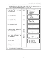
7.8.1 

How to Switch Remote Mode 

Operating procedure 

Operating key

Display 

 Press [MENU] key from the normal 

mode. 

[MENU] 

MENU

1/1

F1 : PARAMETERS

F2 : PROGRAMS

F3 : REMOTE


  Select [F3:REMOTE ] 

[F3] 

REMOTE

1/1

F1 : REMOTE


  Select [F1:REMOTE ] 


Mode changes to remote mode. 

[F1] 

REMOTE

EXIT


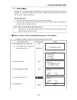
7.8.2  How to Switch Remote Mode to Normal Mode (Manual mode) 

Operating procedure 

Operating key

Display 


REMOTE

EXIT


  Press [F1] (EXIT) key of remote mode. 

[F1] 


Input 

secret code 

REMOTE

SECRET :

EXIT


  Input secret code when secret  mode is 

ON, and press [ENT] key. 

1) 


[ENT] 

REMOTE

1/1

F1 : REMOTE


 Press [ESC] key, and press [MENU] 

key. 


Mode will be changed to normal mode. 

[ESC] 

[MENU] 


1)  If the secret code that is already set is mis-input, it is not possible to change to normal mode. 


Содержание AP-L1A

Страница 1: ...INSTRUCTION MANUAL AUTOMATIC TRACKING TOTAL STATION AP L1A AP L1AN...

Страница 2: ...tribrach is not installed correctly measuring precision may be effected Occasionally check adjusting screws of the tribrach Lock the base fixing lever and tighten the Base Fixing Screw Guarding the i...

Страница 3: ...ve lens side downward Storing it in the case in any other way may cause damage Hold upper and lower hand grips with both hands when taking the instrument out of the case or putting the equipment in th...

Страница 4: ...ver look at the laser beam directly 2 Disassemble reconstruct or repair of the instrument is only to be performed by Topcon or its authorized dealer AP L1A L1AN is not explosion proof Avoid using in a...

Страница 5: ...e but we request you to keep and understand Safety standard for users as mentioned in the manual instruction In case of any failure do not disassemble the instrument Contact TOPCON or your TOPCON deal...

Страница 6: ...ADIATION DO NOT STARE INTO BEAM Maximum output 0 5mW Wave length 685nm CW CLASS 2 LASER PRODUCT Each label is differed by the market Certification and identification label TOPCON AMERICA CORPORATION 6...

Страница 7: ...8 2 Using Software Key to Rotate AP L1A 1 10 1 8 3 Auto Inversion Key 1 11 1 8 4 Telescope Rotating Free Lever and Horizontal Rotating Free Lever 1 11 Attaching Precaution Label 1 11 2 PREPARATION FOR...

Страница 8: ...ONS 7 1 7 1 How to Cancel Error of Automatic Tracking Optical Axis 7 1 One Set of Inverted Observation 7 1 7 2 Area Setting 7 2 7 2 1 Setting Area 7 3 7 2 2 Area Set Function ON and Set Effective Area...

Страница 9: ...REFRACTION AND EARTH CURVATURE 12 1 12 1 Distance Calculation Formula 12 1 13 POWER SOURCE AND CHARGING 13 1 13 1 External Battery Mark Light Battery 13 1 14 DETACH ATTACH OF TRIBRACH 14 1 15 SPECIAL...

Страница 10: ...the Vertical Cross hair 17 6 17 3 4 Collimation of the Instrument 17 7 17 3 5 Checking Adjusting the Optical Plummet Telescope 17 8 17 3 6 Adjustment of Vertical Angle 0 Datum 17 9 17 4 How to Set the...

Страница 11: ...rain cover 1set Plumb bob set 1pc Carrying case 1pc Instruction manual 1vol Field chart 1vol Precaution label 1set The plumb bob hook rod pins screwdrivers cleaning brush fuse 4A and silicone cloth ar...

Страница 12: ...rotating free lever Tracking indicator Fuse holder 4A Base fixing screw Base Leveling screw Serial Signa Connector Port 1 Horizontal shuttle Power supply connector DC12V Horizontal jog Power key Auto...

Страница 13: ...lever Certification and identification label 2 Adjusting screw for circular level Circular level Horizontal rotating free lever Optical plummet telescope Optical plummet eyepiece Optical plummet focu...

Страница 14: ...1 NOMENCLATURE AND FUNCTIONS 1 3 2 The details of label will be differed by the market...

Страница 15: ...isplay s speed up at temperatures lower than 0 degrees C Example V 90 10 20 HR 120 30 40 0SET HSET R L 1 Angle measurement mode V angle 90 10 20 H angle 120 30 40 0SET HSET R L Searching 0SET HSET R L...

Страница 16: ...D VD NEZ Coordinate meas key Coordinate measurement mode A M Auto Manual key Switches auto tracking and manual mode MENU Menu key Switches menu mode and normal mode It is enable to set an application...

Страница 17: ...soft keys shown in the next page 2 90 F1 90 Rotation Instrument rotates 90 horizontally to the clockwise direction 90 F2 90 rotation Instrument rotates 90 horizontally to the counter clockwise directi...

Страница 18: ...ts an instrument coordinate point by input values RST F3 Resection Sets instrument coordinate point from two known points and their measured values 5 F4 Page The function of soft keys shown in the nex...

Страница 19: ...Transmit command for battery level The battery level will be out put Transmit command for coordinate of instrument point Setting coordinate of instrument point will be out put Transmit command for tr...

Страница 20: ...rminal WT 1A 1B 2 Data terminal FS 2 1 The type of interface cable will differ by the market 2 The wireless terminal WT 1A 1B shape will differ by the market 1 6 1 Setting Wireless Modem AP L1A only T...

Страница 21: ...sphere condition such as rain or fog or the presence of another type of radio wave or magnetic noise the communication distance can be shortened Antennas for AP L1A and wireless terminal WT 1A 1B oper...

Страница 22: ...is function can be used to level the instrument very accuracy with plate level after power ON Go to page two of the options by pressing F4 key Select the required rotating angle by F1 to F3 key respec...

Страница 23: ...the storage marks or to rotate the telescope before loading into the case Insufficient use of levers may cause damage to the drive unit Do not use these levers except for storing Never touch these lev...

Страница 24: ...tions requires power Level and center the instrument precisely to insure the best performance It is recommended to use the Topcon Wide Frame Wooden tripod such as TP 10 Type E 2 2 Connecting Power Sup...

Страница 25: ...to the center of the plate level by turning leveling screws A and B Rotate the instrument 90 100g around its vertical axis and turn the remaining leveling screw or C to center the bubble once more Re...

Страница 26: ...SET H SET AUTO V SET AUTO BATT Body and Telescope rotates automatically to be ZERO SET ZERO SET H SET MANU V SET MANU BATT Rotate telescope and body by operating H V shuttle for ZERO SET V 90 10 20 HR...

Страница 27: ...ing light and battery mark for battery indicates the level of power for the Mark Light power source Press Battery check switch Remaining battery mark light to show the battery level Decreasing Note 1...

Страница 28: ...he previous mode It does not memorized this setting after power OFF To set auto tilt correction from the moment that power is on refer to chapter 16 Selecting Mode The display of Vertical or Horizonta...

Страница 29: ...N OFF Press F1 ON key 1 F1 1 V TILT ON 2 V H TILT ON 1 2 EXIT Press F4 EXIT key after confirming that gV H TILT ON is selected F4 V 90 10 20 HR 120 30 40 TILT m f 3 The setting mode performed here wil...

Страница 30: ...s will be proportional to the misalignment as showing in following graphs The more misalignment of the prism the more error in measurement Measured data can be different according to the prism constan...

Страница 31: ...0m by Prism type 2 Distance error is From the graph prism type 2 the distance error shows in increasing range quantity 2 5mm along curved line of C 0 when prism inclination is 20 Angle error is From t...

Страница 32: ...unction keys 3 V 90 10 20 HR 120 30 40 SD m 0SET HSET R L If the target prism is lost during auto tracking status the instrument will automatically change to Waiting status and symbol mark will be swi...

Страница 33: ...ving or unstable objects The fine mode is for objects which are fixed and or for precise measurements Please refer to chapter 5 4 Fine Mode and Coarse Mode 4 While the instrument is in the Waiting sta...

Страница 34: ...isplayed V 98 10 20 HR 160 40 20 0SET HSET R L 1 Note From a known coordinate value of the instrument point and the backsight point the AP L1A can set a directional angle See chapter 6 1 Setting a Dir...

Страница 35: ...viewing vertically or horizontally while looking into the telescope focusing is incorrect or diopter adjustment is poor This adversely affects precision in measurement or survey Eliminate the paralla...

Страница 36: ...e measurement Operating procedure Operating key Display V 90 10 20 HR 120 30 40 0SET HSET R L 1 Press F3 R L key The mode Horizontal angle Right HR switches to HL mode F3 V 90 10 20 HR 239 29 20 0SET...

Страница 37: ...H SET HR EXIT CLR Input value of Horizontal angle to be set For example 70 40 20 1 7 0 4 0 2 0 H SET HR 70 4020 EXIT CLR Press ENT key ENT H SET HR 70 40 20 SET When completed normal measuring from t...

Страница 38: ...OVING V 93 10 40 HR 160 20 10 EXIT CLR Input the horizontal angle to be rotated and press ENT key For example 160 20 10 ENT 1 6 0 2 0 1 0 The instrument will start to rotate 2 ENT MOVING V 93 10 40 HR...

Страница 39: ...stance measurement starts 1 2 V 90 10 20 HR 120 30 40 SD m 0SET HSET R L 1 The measured slope distances show every 0 2 to 4 5 seconds according to setting of distance measuring mode 3 6 V 90 10 20 HR...

Страница 40: ...0 2 seconds Measurement accuracy 10mm 2ppm m s e Use this mode for auto tracking measurement Operating example Operator chooses to change from the Fine to Coarse mode with a 1cm measuring unit Operati...

Страница 41: ...r 6 2 Setting coordinate of instrument point Press F4 key 4 times to be function as in page 5 Press F1 BS key Screen is displays INPUT of Backsight point Input N and E coordinate of backsight point A...

Страница 42: ...will need to be reentered 6 2 1 How to Input Instrument Coordinate Value Directly Confirm the mode is set in angle or distance measuring mode Example N coordinate 12 345m E coordinate 54 321m Z coordi...

Страница 43: ...Z 2 3450 m INS HT 1 3000 m EXIT CLR SET OK YES NO Press F3 YES key At the end of setting the mode returns to the previous setting F3 V 90 10 20 HR 120 30 40 BS CSET RST 5 1 When Z coordinate is not in...

Страница 44: ...nverted measurement Confirm mode is angle or distance measurement Operating procedure Operating key Display Press F4 key 4 times to be a function as in page 5 F4 4 times V 90 10 20 HR 120 30 40 0SET H...

Страница 45: ...ng the tracking condition automatically 3 When measurement of the known point A is completed measurement of the known point B starts F3 or REC V 90 10 20 HR CHECKING MEASURING SET 10 20 30 V 90 10 20...

Страница 46: ...NT A 2 CHECKING MEASURING SET RETURN A dVA 0 00 10 dVA 0 00 15 dH 0 00 05 SET OK YES NO 14 Confirm the vertical angle error and horizontal angle discrepancy and press F3 YES key 6 Discrepancy dHD and...

Страница 47: ...key is pressed the procedure returns to step 7 Error will be displayed when the angle of dHD or dZ is exceeded 999mm and the display changes to select for remeasurement Press F3 YES key to select reme...

Страница 48: ...displayed Enter the instrument height and press ENT key If the value is accepted press ENT key as it is F2 Input Inst HT ENT INS HT INPUT 0 0000 m EXIT CLR INS HT INPUT 1 3000 m EXIT CLR SET OK YES NO...

Страница 49: ...T or REC key Measurement will be done 2 times The screen displays for the selection of measurement in inverted position after measurement of the known point B is completed F3 or REC V 90 20 30 HR 70 3...

Страница 50: ...ed the display returns to the previous measurement mode 8 F3 V 90 10 20 HR 10 20 30 BS CSET RST 5 1 Selecting 2D will be omitted following input of instrument height Z Coordinate value and prism heigh...

Страница 51: ...te value of known point A and B Z coordinate discrepancy dZ dZ Z coordinate value of the instrument calculated from measured value of known point A Z coordinate value of the instrument calculated from...

Страница 52: ...1 3m Operating procedure Operating key Display Press F4 key 5 times to be a function as in page 6 F4 5 times V 90 10 20 HR 120 30 40 0SET HSET R L 1 MOVE R HT 6 Press F2 R HT key F2 REFLECTOR HIGHT R...

Страница 53: ...E1 Z1 can be calculated as following formula Coordinates of instrument point N0 E0 Z0 Instrument height INS HT Prism height R HT The coordinates of prism center originated from the center point of th...

Страница 54: ...ts The result of measurement is shown NEZ N 35 678 m E 67 543 m Z 2 354 m 0SET HSET R L 1 1 In case the coordinate of instrument point is not entered 0 0 0 will be used as the default for the instrume...

Страница 55: ...face 2 reversed position of the telescope The theory for canceling is the same as used for compensating for vertical axis error or horizontal axis error The calculations and procedures are similar Aut...

Страница 56: ...When area set is On you can not sight outside the area set even in manual mode Reversing the telescope is possible with set area by auto inversion key or turn over command Don t use telescope rotatin...

Страница 57: ...area range will not effect area range No need to input area again 1 Setting by sighting directly Operating procedure Key Operation Display Press MENU key in the normal measurement mode MENU MENU 1 1 F...

Страница 58: ...area No 1 To set another area repeat from the step of F3 AREA SET F1 INPUT NEZ F2 MOVED SET F3 SETTING AREA 11 Press F1 EXIT key Menu returns to AREA SET 1 1 Pressing ESC key from the AREA SET menu r...

Страница 59: ...m E m EXIT CLR B 2 Input coordinate value of point B and press ENT key N Coord ENT E Coord ENT Z Coord ENT AREA SET Z 4 5678 m EXIT CLR SET OK YES NO B 2 Press F3 YES key The area range to be set is...

Страница 60: ...TE Select F2 PROGRAMS F2 PROGRAMS 1 1 F1 TEACH F2 AREA SET Select F2 AREA SET F2 AREA SET F1 INPUT NEZ F2 MOVED SET F3 SETTING AREA Select F2 SETTING AREA F2 AREA MODE OFF EXIT ENT Press F2 F3 key and...

Страница 61: ...e prism which is still or almost still Required measuring accuracy in still condition but not tracking performance during traveling prism Suitable for fixed point observation management of landslides...

Страница 62: ...Example Tracking is not possible Tracking is possible The following table shows minimum tracking distance by each scanning range and a prism type in auto tracking mode WIDE 60 60 MIDDLE 40 40 NARROW 2...

Страница 63: ...e rotating method of telescope and instrument to find the target prism in search mode Search pattern includes the following 2 ways that can be selected High speed This pattern can be selected to searc...

Страница 64: ...ecording data timing at one person surveying Meaning of Tracking Indicator ON or Flashing Tracking Indicator Status of instrument Continuous ON Search or Wait status in auto mode Slow flashing Manual...

Страница 65: ...ase of traveling objects moving fast measurement in fine mode can not be performed Also if unstable measuring light quantity is experienced this can be the cause of automatic remeasuring so that the p...

Страница 66: ...and 46CH in case using 2 sets of AP L1A and WT 1A 1B 2 Avoid radio disturbance by tertiary intermodulation in case using 3 radio sets or more Radio disturbance by tertiary intermodulation meaning tha...

Страница 67: ...change channel number carry out in normal mode or power off state Whatever the rotary switch is changed in remote mode wireless communication mode the actual channel is not changed Same as WT 1A 1B i...

Страница 68: ...ote Never forget the secret code which you set If forgotten you can not operate any function on the AP L1A and it must be returned to an authorized Topcon dealer for repair How to Set Secret Code and...

Страница 69: ...F2 SECRET CODE Select F1 SECRET MODE Press F2 F3 key select ON and press F4 ENT key F1 F4 or F3 F4 SECRET ON EXIT ENT SET SECRET F1 SECRET MODE F2 SECRET CODE Power OFF 1 If the secret code that is a...

Страница 70: ...emote Mode Operating procedure Operating key Display Press MENU key from the normal mode MENU MENU 1 1 F1 PARAMETERS F2 PROGRAMS F3 REMOTE Select F3 REMOTE F3 REMOTE 1 1 F1 REMOTE Select F1 REMOTE Mod...

Страница 71: ...e used in survey or stake out in AP L1A Setting an area is not always necessary but may prove to be convenient to find the lost prism for re tracking or to avoid unnecessary tracking to the other refl...

Страница 72: ...data terminal for tracking status Display shows the distance and direction between AP L1A and target Execute survey or stake out When surveying or stake out is completed the first point move to second...

Страница 73: ...er is suitable to the situation of measuring field Setting of tracking speed is very important In Teach measurement mode the tracking speed in LOW Speed is suitable 3 Set each control point measuring...

Страница 74: ...f same point in both faces of AP L1A Press F2 F3 key and select ON OFF and press F4 ENT key F2 F2 or F3 ENT R 1 1 ON EXIT ENT TEACH POINT 1 V 98 46 55 H 210 55 25 EXIT RL MEAS ENT Press F3 MEAS key Se...

Страница 75: ...ect F1 SEARCH F1 SEARCH ON OFF ON EXIT ENT Press F2 F3 to select ON OFF SEARCH function and press F4 ENT key F2 or F3 ENT PARAMETERS F1 SEARCH F2 EDM MODE F3 CYCLE TIME Select F2 EDM MODE F2 EDM MODE...

Страница 76: ...easuring is carried out by order of control points from small to large If data is not ready to be measured the specific point will be disregarded Press ESC key to cancel measurement Auto Area Setting...

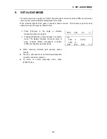
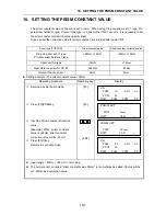
Страница 77: ...get is difficult to find Press F4 key in the angle or distance measuring mode as in page 4 Pressing F3 S A key mode changes to set audio mode The display indicates correction value of prism constant P...

Страница 78: ...22mm or 0mm 22mm or 0mm Prism unit A2 type 14mm 14mm Near distance prism for AP S1 22mm 22mm Normal Topcon prism 0mm 0mm Setting example The prism constant value 22mm Operating procedure Operating ke...

Страница 79: ...ction is obtained as follow L l 1 Ka l Measured distance when atmospheric correction is not set Example In case Temperature 20 C Air pressure 635mmHg l 1000 m Ka 279 66 106 033 635 273 15 20 10 6 50 1...

Страница 80: ...orrection Value Directly Measure the temperature and air pressure to find atmospheric correction value PPM from the chart or correction formula Example Atmospheric correction value 6 ppm Operating pro...

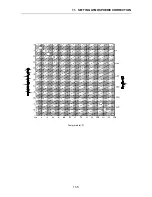
Страница 81: ...the atmospheric correction chart Find the measured temperature in horizontal and pressure in vertical on the chart Read the value from the diagonal line which represents the required atmospheric corr...

Страница 82: ...11 SETTING ATMOSPHERIC CORRECTION 11 4 Temprerature C Temprerature F...

Страница 83: ...11 SETTING ATMOSPHERIC CORRECTION 11 5 Temprerature F...

Страница 84: ...taken into account Follow the Formula below for the converting horizontal and vertical distances Horizontal distance D AC or BE Vertical distance Z BC or EA D L cos 2 sin Z L sin cos L cos 2R Earth c...

Страница 85: ...ight battery or ambient temperature of operation especially in a low temperature Mark light battery Notes 1 Recharging should take place in a room with an ambient temperature range of 10 C to 40 C 50...

Страница 86: ...e on the lower part of the instrument with the tribrach alignment groove Tighten the tribrach fixing lever firmly by turning clockwise Tighten the tribrach fixing screw Locking the Tribrach Fixing lev...

Страница 87: ...H F1 PATTERN F2 AREA F2 WAIT TIME F3 SCAN WIDTH F1 ADJ AXIS M F2 ADJ AXIS A F3 TRK SPEED F1 TRK SENSITIV F2 MEAS F1 TILT ON OFF F2 DATE TIME F3 OCC POINT F1 RST A M F3 COM F1 COM1 F1 BIT FORMAT F2 TRA...

Страница 88: ...time from factory is Normal H 10 V 2 High H 10 V 10 2 WAIT TIME Setting the waiting time The time the prism is lost before AP L1A starts the SEARCH during Tracking mode If the mode is set in HOLD mode...

Страница 89: ...Low speed MEDIUM Medium speed HIGH High speed Setting value at shipping time from factory is MEDIUM 6 TRK SENSITIV Setting Tracking detecting sensitivity Refer to Chapter 7 3 Setting tracking paramet...

Страница 90: ...tion Press MENU key from the distance or angle measuring mode MENU Select F1 PARAMETERS F1 Select F2 MEAS F2 Select F2 DATE TIME The display shows date and time which is already set F2 Press F3 YES ke...

Страница 91: ...t stop 2 EVEN D7 S1 EVEN 7bit stop 1 EVEN D7 S2 EVEN 7bit stop 2 EVEN D8 S1 ODD 8bit stop 1 ODD D8 S2 ODD 8bit stop 2 ODD D7 S1 ODD 7bit stop 1 ODD D7 S2 ODD 7bit stop 2 ODD Setting value at shipping...

Страница 92: ...p 2 EVEN D7 S1 EVEN 7bit stop 1 EVEN D7 S2 EVEN 7bit stop 2 EVEN D8 S1 ODD 8bit stop 1 ODD D8 S2 ODD 8bit stop 2 ODD D7 S1 ODD 7bit stop 1 ODD D7 S2 ODD 7bit stop 2 ODD 2 2 TRANS SPEED Communication S...

Страница 93: ...le sight Setting times 1 Measuring time 100 Initial value 1 1 2 DELETE Deleting a measuring point Delete useless measured point among measuring points See Chapter 8 2 Teach measurement how to operate...

Страница 94: ...e time The cycle time represents the elapsed time from the start of Teach measuring through to the last point and to when user wants to repeat the process with the same points all over again Setting n...

Страница 95: ...nction for setting area User may set from one to four set areas 15 3 REMOTE 15 3 1 REMOTE Remote Mode Wireless communication mode The remote mode is to communicate between AP L1A and wireless terminal...

Страница 96: ...lect F1 SEARCH F1 SEARCH PATTERN HIGH EXIT ENT SET Select F1 PATTERN Select pattern by pressing F2 key or F3 key and press ENT key Example HIGH F1 F2 or F3 ENT SEARCH F1 PTTERN F2 AREA The display ret...

Страница 97: ...S 1 1 F1 TRK F2 MEAS F3 COM Select F3 COM F3 COM 1 2 F1 COM1 F2 COM2 REMOTE Select F1 COM1 F1 COM1 F1 BIT FORMAT F2 TRANS SPEED F3 TERMINATE Select F2 TRANS SPEED 1 F2 TRANSMIT SPEED 1 4800 EXIT ENT P...

Страница 98: ...N in F3 HA 0 INDEX V H AUTO F2 MIN ANGLE 1 0 2mgon 0 01mil Selecting minimum unit for angle measurement DEG 1 5 GRAD 0 2mgon 1mgon MIL 0 01mil 0 1mil 5 1mgon 0 1mil F2 DIST F1 UNIT METER Choose measur...

Страница 99: ...16 SELECTING MODE 16 2 F2 SECRET CODE Set Secret code Setting secret code in 4 digits for SECRET function...

Страница 100: ...e which was set previously In case the secret code is not set the selecting menu is displayed Secret code already set PARAMETERS F1 ANGLE F2 DIST F3 SECRET Select F1 Angle F1 PARAMETERS 1 2 F1 UNIT F2...

Страница 101: ...E F3 EDM MODE FINE 0 2mm EXIT ENT Press F2 or F3 set COARSE 1 cm mode Press F4 ENT key F2 or F3 F4 EDM MODE CRS 1cm EXIT ENT SET Display returns to PARAMETERS 1 1 menu PARAMETERS 1 1 F1 ANGLE F2 DIST...

Страница 102: ...please note that the difference in temperature greatly changes the length measured in the building If a difference of 5mm or over is the result from the comparative measurement the following procedure...

Страница 103: ...sm center gradually until at the position buzzer starts Confirm the value of SIG light quantity level in display to adjust at the level of 1 to 20 by turning the horizontal jog Press the ESC or F1 EXI...

Страница 104: ...al direction confirmation Compare the reading Vertical angle value and calculated value If the difference is within 1 30 no problem for use Example 90 12 30 90 04 30 Average 90 08 30 Difference 20 Rea...

Страница 105: ...always tighten by revolving in the direction of tightening tension The attachment screws must also be tightened sufficiently upon completion of adjustments Always repeat checking operations after adj...

Страница 106: ...lacement by this method Correct the remaining amount of the bubble displacement with the leveling screws Rotate the instrument 180 or 200g around the vertical axis once more and check bubble movement...

Страница 107: ...rom the vertical cross hair as the telescope is swung vertically adjustment is required in the reticle plate Adjustment Unscrew the cross hair adjustment section cover by revolving it in the countercl...

Страница 108: ...e the vertical jog and shuttle only and rotate the telescope 180 or 200g around the horizontal axis once more and fix a sight on Point C which should coincide with previous Point B If Points B and C d...

Страница 109: ...tical axis and check the center mark If the point is properly centered in the center mark adjustment is not required Otherwise adjust in the following manner Adjustment Unscrew the adjustment section...

Страница 110: ...for H and V angle When mode is set in manual 0 set turn jog shuttle of H or V 0 set F1 POWER ON V0 ADJUST ZERO SET H SET AUTO V SET AUTO Operate jog shuttle of H and V and collimate target A from the...

Страница 111: ...not set the selecting menu is displayed PARAMETERS F1 ANGLE F2 DIST F3 SECRET Select F2 DIST F2 DIST 1 3 F1 UNIT F2 W CORR F3 EDM MODE Press F4 key DIST 2 3 menu will be displayed F4 DIST 2 3 F1 OFFSE...

Страница 112: ...Datum Also auto adjustment is not possible when error is exceeding 1 You must adjust manually 1 Auto Adjustment Procedure After doing Chapter 17 3 4 Collimation of the Instrument and Chapter 17 3 6 Ad...

Страница 113: ...turn at the normal direct position of telescope The shifted quantity between H angle and V angle measured from the normal and reverse position of telescope will be calculated internally and the error...

Страница 114: ...F3 SCAN WIDTH Press the F4 key TRK menu 2 3 will be shown F4 TRK 2 3 F1 ADJ AXIS M F2 ADJ AXIS A F3 TRK SPEED Select F1 ADJ AXIS M F1 ADJ AXIS M PRISM COLLIMATE SET OK YES Adjust H V jog shuttle unti...

Страница 115: ...lescope reticle and the center of prism is coincided If not repeat from the procedure TRK 2 3 F1 ADJ AXIS M F2 ADJ AXIS A F3 TRK SPEED 1 The display shows NOT TRACKING when tracking mode is not set or...

Страница 116: ...m 0mm Prism unit A3 type Prism constant 0mm Target pole 2 not used with 9 prisms Tribrach Tribrach adaptor S2 Tribrach adaptor 3 9 prism holder 2 Tilting prism holder 1 Tilting prism holder 2 Target p...

Страница 117: ...xternal dimensions 260 L 91 W 184 H mm Weight 3 2kg Battery charger for mark light battery Input voltage Changeable AC100 120V 220 240V External dimensions 139 L 143 W 83 H mm Weight 2 4kg Wireless te...

Страница 118: ...1 A case to store and carry accessories External dimensions 300 L 145 W 220 H mm Weight 1 4kg Back pack Model 2 Convenient for use in mountainous terrain Prism unit case Model 6 Fixed 9 prisms unit ca...

Страница 119: ...oil or paste moistened with mixed liquid 2 For the dirt on plastic parts avoid to use of volatile material such as thinner or benzene but use neutralized detergent or water 3 Keep the telescope horiz...

Страница 120: ...ng system Switch OFF the power then ON again Sometimes error occurs when vibrates clear the vibration E11 Displayed when the input value for instrument constant value exceeds the input range Input pro...

Страница 121: ...mality in distance measuring system Instrument in need of attention from authorized repair facility E71 Displayed when vertical angle 0 position is set with incorrect procedure After confirmation proc...

Страница 122: ...3 or 5 with 1 prism 12 700 m 40 2 300ft 6 700m 20 2 300ft 4 700m 13 2 300ft Prism Unit Type A2 A3 Prism type 3 6 in all direction 30 500 m 100 1650ft 15 500m 50 1650ft 10 500m 33 1650ft Collimation a...

Страница 123: ...te sunlight with light heat shimmer Measurement range 7 FINE measurement 3mm 2ppm m s e COARSE measurement 10mm 2ppm m s e Possible measurement max prism moving speed in direction of near to far 20 km...

Страница 124: ...n the market 8 The communication distance will be determined by the circumstances of instrument occupation and or radio condition Refer to the instruction manual in detail Others Operating Temperature...

Страница 125: ...Input Voltage DC 12V Power consumption 10 5 18W Operating time Using 90 charged Mark light battery 9 11 Only for Distance and Angle measuring approx 7 hours Auto Tracking of a still object approx 5 h...

Отзывы: