centerline of F-5 up to the top sheeting and the other
from the centerl ine of F-5 down to the bottom edge of
the fuselage. This completes the sheeting of the
front end of the airplane. If you have taken your time
and fitted these pieces with a minimum amount of
gaps, all that remains is sanding to shape.
21. Use a sanding block to bevel the inside ends of the
spruce fuselage framework at the tailpost—see
plans. Once satisfied, glue these ends accurately
together providing equal bends to each side of the
fuselage. Now accurately cut and glue in place all of
the remaining spruce and balsa cross braces as
shown.
22. Once again, accurately position the wing center sec-
tion in place on the fuselage. Using the trailing edge
as your mark, finish sheeting the top of the fuselage,
cross grain, back to the point where the fuselage
sides end. Remove the center section from the
fuselage.
23. With the exception of final sanding and rounding as
shown on the plans, the fuselage is now complete.
LANDING GEAR AND TAILSKID ASSEMBLY
Note that the front and rear 1/8" dia. M.W. landing gear
forms are supplied to you pre-bent. Note on the plans
that they must be joined together at the bottom, towards
the wheels. We recommend soft copper wire for first
firmly wrapping the two pieces together followed by
soldering the legs together. We would highly recom-
mend the use of HARRIS'S STAY-CLEAN FLUX and their
silver solder for this operation. Although a soldering iron
will work with patience, these joints can be quickly and
permanently made with the use of a small hobby-type
gas torch.
1. Locate the position of the rear "crossed-axle" wire
to the bottom rear ply L/G plate on the fuselage bot-
tom. While holding the wire in place, slip the two
formed metal clips onto the wire. Using a pencil to
mark the hole locations of these clips onto the ply
base, remove the wire and clips. Drill shallow, small
diameter "guide holes" for the clip's screws. Now
attach the landing gear wire to the fuselage with the
clips and the #2 x 3 / 8 " screws provided—there is no
need to overtighten them. Repeat this process with
the forward landing gear wire.
2. Pull the two components together until they touch.
The two short bent "arms" on the forward leg should
line-up with the legs of the rear L/G wire. If needed,
use pliers to adjust these arms until they neatly fit.
3. Use soft copper wire to now neatly wrap the forward
short arms to the rear L/G wire as shown on the
plans. Apply some STAY-CLEAN flux to the joint and
solder. Repeat the process on the other side. Be neat
and try and be sure that the joint is at once solid
without a lot of excess solder. Once satisfied, com-
pletely clean the solder joints of any flux.
4. As shown, the crossed-axle landing gear system
derives its ability to accept landing loads and shock
from the two (2) independent axle legs. These need
to be joined at two points, each 2-1/2" in from the
wheels. This distance has shown very good shock-
absorbing ability for Elders weighing 3-3-1/2 lbs. Join
these axles by first measuring the 2-1/2" distance re-
quired, wrapping with soft wire (about 3/8") and
soldering. Again, clean the solder joints completely.
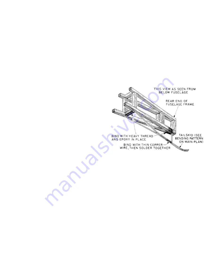
5. The same process is now used to make the rear
tailskid assembly. First bend the 1/16" dia. M.W. pro-
vided to the shape shown using pliers. Wrap the tip
of the skid with soft copper wire and solder. Now
tape the main skid wire in place to the bottom'rear of
the fuselage. Locate the pre-bent tailskid support
wire and wrap it in place to the tailskid with soft wire.
Solder it in place to the skid. Remove the assembly
from the fuselage and again, clean the solder joints
completely.
6. Remove the main landing gear from the fuselage.
The landing gear and tailskid are now complete and
can be used as is or painted flat black or aluminum
(we use K&B epoxy paints for this as well as other
painting needs on this airplane). As we did on some
of our prototypes, you may wish to add wood back-
ing to the wires, sand these to airfoil shape and paint
them a wood color—looks great! We used 1/8" x 1/4"
hard balsa with a 1/8" dia. "groove" sanded into one
edge, carefully fitting the piece in place. We glued
the wood to the metal with thick CA adhesive and
sanded the whole affair smooth. Then we used clear,
paintable Monokote to cover the "wooded" parts of
the landing gear to provide a one-piece look and air-
brushed wood-colored epoxy paint on the whole
thing.
FINAL ASSEMBLY
1. Locate one of the 1/4" dia. by 3-1/2" dowels. Insert the
dowel into the hole previously drilled in the leading
edge of the wing center section. As shown on the
plans, it extends all the way back to the main wing
dihedral brace with about 1/4" - 3/8" of it extending
out to connect with the F-7/F-8 formers; trim the
length as needed. Now install the center section to
the wing with the forward dowel in place. Liberally
8


