way, when the fuselage is done, your tank can be in-
serted from the wing opening into the nose and
removed, if needed, with assurance that it is
mounted correctly. Now use a 3/16 "drill bit to drill the
two required holes for the fuel tank (one for fuel feed
and filling and the other for the pressure tap and
overflow). Remove the tank.
12. Drill and tap the holes necessary In the motor mount
to attach your engine (we like to use 4-40 Allen-head
bolts for this purpose). Attach the motor mount to
the firewall and the engine to the mount. By viewing
from the front, determine the location of the throttle
tube housing exit hole. This should be lined-up with
the carb's throttle arm. Drill a 3/16" dia. hole through
the firewall for this tube. Rough-up the outer surface
of the outer throttle tube housing and glue it in place
in the firewall—about 3/16" of it should protrude out
from the face of the firewall, the rest of it runs into
the radio compartment. Be sure your tank still fits
nicely.
13. The servos shown on the plans are of average con-
figuration, however yours may be different; taller,
wider, etc... The Elder will accept almost any radio
system, there is plenty of room. Lay the fuselage
frame over the side view of the plans and take one of
the servos that you plan to use and lay it in place,
about where they are shown on the plans.
Remember that these servos will be mounted on the
1/8" ply servo tray. Observe if your servos will fit. Cut,
fit and glue the 1/4" x 1/2" balsa servo tray bearers in
place between the two uprights in the radio (servo)
compartment—note that their outer edges are flush
with the rest of the fuselage frame
14. You can now sheet the bottom of the fuselage from
the nose (between the two landing gear formers)
back to the last bottom 1/4" x 1/2" cross brace—don't
sheet any further back. Note this sheet is applied
cross grain. Use your sanding block to clean the
edges flush with the frame sides. Sand the landing
gear mounts and sheeting to a smooth curve when
viewed from the side.
15. Use the 3/32" x 4" x 24" balsa sheet provided to now
make the primary fuselage sides. Be economical
here, you will need the rest of this sheeting later. Lay
the fuselage frame on the sheet with the forward
edge of it lined-up with the leading edge of the wing.
Use a pencil to trace the fuselage side outline onto
the sheeting. Cut out the fuselage side and glue it in
place, repeat the process for the other side. Use your
sanding block to again true-up edges and generally
tidy the fuselage.
16. Stand the fuselage on its nose, firewall flat to the
work surface. Locate and glue in place the two side
F-4 formers to the firewall sides, flush with its front
face.
17. Locate and glue in place the two side formers, F-5.
Glue balsa former F-7 to ply former F-8 (see plans).
Glue the F-7/F-8 former in place at the top of the
fuselage where the leading edge of the wing will be.
18. Locate and accurately pin in place the wing center
section to the top of the fuselage—take your time
and locate it as accurately as possible. Use a 1/4"
dia. drill to drill through F-7, F-8, the leading edge
and dihedral brace of the center section—back up
the dihedral brace with a piece of scrap wood to
avoid splintering as the drill bit passes through it.
Remove the center section and set aside for now.
Once again stand the fuselage on it's nose, flat on
the work surface and glue the top F-3 former in place
on top of the firewall and flush with it's front face.
19. Measure, cut and glue in place the top 1/4" sq. balsa
cowl longeron from F-7 through F-3 and out past the
firewall as shown on the plans to pick-up F-2. Cut, fit
and glue the two side 1/4" sq. balsa cowl longerons
to the slots in the F-4's. Now fit in place cowl former
F-2, don't glue yet. Observe how this former is fitting
in place, make sure that it is parallel with the firewall
and that when viewed from the side it is also parallel
with the firewall. Once satisfied, glue it to the three
1/4 " sq. balsa longeron ends. Now glue the two F-1
cowl pieces to the front face of F-2, leaving a 3/32"
"shelf" for mounting the cowling sheet.
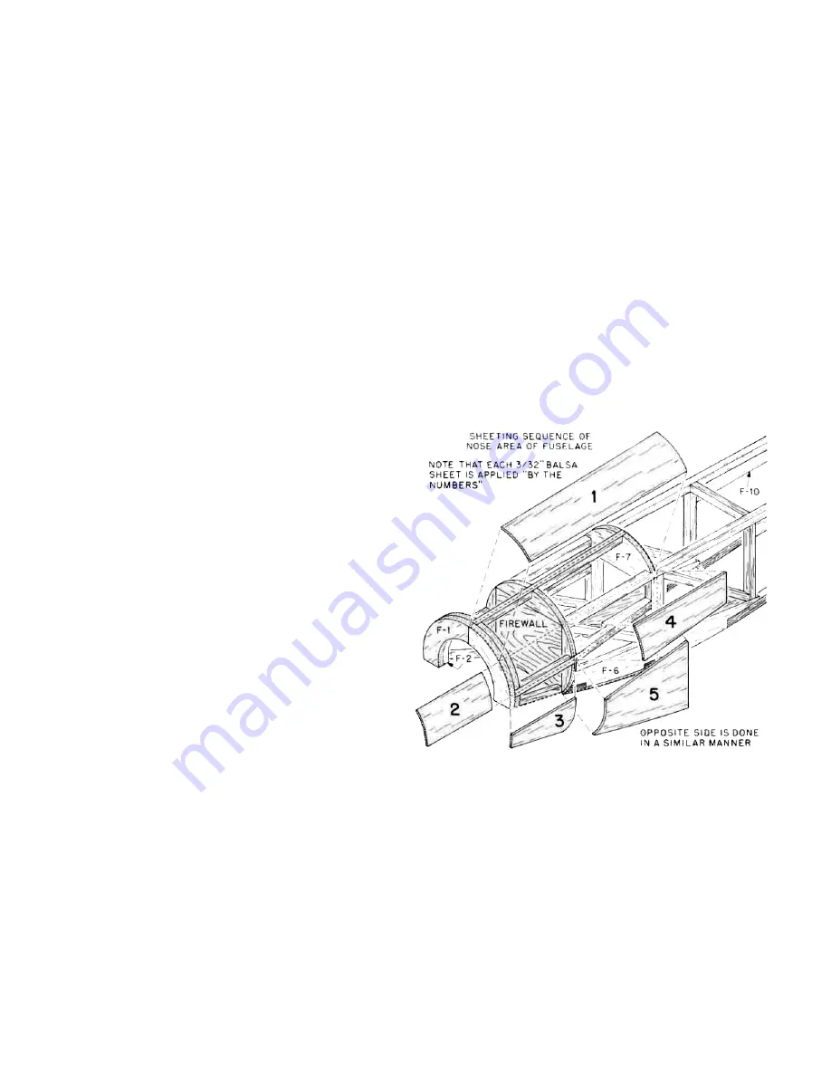
20. You are now going to sheet the nose of the fuselage
as follows: Start by sheeting the top of the fuselage
from F-7 out to F-2. Do this in two pieces with the
seam on the centerline of the top 1/4" sq. balsa
longeron. Wetting the top of the sheet (3/32" balsa
through-out) will help conform it to the formers. Use
thick CA adhesive for this operation; in that way no
pins or tape will be needed. Next, cut and fit a piece
of sheeting that will fit against the edge of the top
sheet, extend down to the centerline of the side 1/4"
sq. balsa cowling longeron and fit between F-1 (on
the top of F-2) and half the thickness of F-4. The next
piece butts up against the edge of the last piece just
installed, down to the bottom of F-1, angling back to
the bottom of F-4. This then leaves only the sides of
the fuselage open at the tank compartment. This
area is done in two pieces also. One from the
7


