


❏
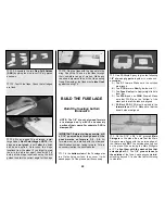
2. Cut 3/16” square balsa Stringers to fit from
F-1B to IP. Glue them in position with thin CA.
❏
3. Use the pattern on the wing plan to cut an
Upper Side Panel (not to be confused with Top
Panel) from a 3/32” x 2-3/4” x 24” balsa sheet.
The curved portion should be sanded for a snug
fit under the Stab when the bottom of the sheet
is on the Main Sub-stringer. Trim the length to fit
flush with the Cabin Side and the aft end of the
Stab. The top edge should bisect the stringer.
Dampen the outside surface of the sheet, flex it
to star t a cur ve, then glue it in place with
medium CA. Repeat this step for the other side
of the fuse.
IMPORTANT
: Be sure to get a good
glue bond between the sheeting and the bottom
of the Stab.
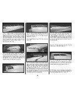
❏
4. Once again, use the pattern on the wing
plan to rough cut the Top Panel from a 3/32” x
2-3/4” x 24” balsa sheet. This time, carefully
sand the aft areas to fit closely with the Stab and
the Fin. Tr im the length even with the
overhanging stringers at F-5B. The Top Panel
should bisect the top center stringer. Repeat this
step for the other side. Use the chalk technique
to mark the top center cut line.
❏
5. Use the off-cut pieces of 3/32” balsa from
the lower fuse sheeting to sheet the area from F-
1B to 1-1/2”
past the Instrument Panel
. The
easiest way to do this small section is to make a
“skin” by edge gluing three sheets together, then
cutting them as a unit to fit over the front end of
the fuse.
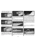
❏
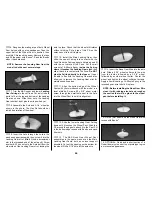
6. Refer to the shape of the Instrument Panel
anti-glare shield on the plans, then carefully cut
and sand the top forward sheeting to conform to
this shape.
❏
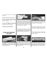
7. Sand off the protruding portion of the Main
Sub-Stringer
ledge from along both sides of the
fuse with a T-bar or sanding block.
❏
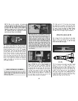
8. Draw a centerline from the middle of the Fin
LE along the top of the fuse to F-5B. The tip of
the center stringer may be used for reference.
Use the plans as a guide to spot glue the die-cut
3/32” balsa
Dorsal Fin Former D-3
in position.
It must be centered on the centerline you drew.
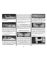
9. Measure and cut a 7/32” x 1/2” x 15” tapered
balsa
Top Edge
stringer (leftover from the wing
center section TE) to fit from the Fin’s LE to the
top of the fuse, as shown on the plans. Glue it in
position. Slide die-cut 3/32” balsa
D-1
and
D-2
under the Top Edge stringer until they fit. Glue
them in position.
❏
10. Hold a 1/16” x 3” x 30” balsa sheet against
the Dorsal Fin framework and trace the outline,
allowing a little extra for sanding
. Bevel the aft
edge to fit the curvature of the Fin at the LE.
Glue the sheet to the Dorsal Fin’s frame and to
the fuse top sheeting being careful
not to build
in any twists
. Repeat this step for the other side.
40


