


NOTE: Due to the variety of hook-up
methods preferred by different modelers, we
do not provide any throttle linkage hardware
in most of our kits. However, we do offer the
following method as one that works well.
You probably have the materials buried
somewhere under your workbench.
❏
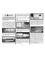
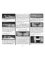
7. Insert a short length of outer pushrod tube
through the throttle hole in the Firewall. Attach a
Ball Link to the throttle arm on the engine. Screw
a Ball Link Socket onto a 2-56 x 12” threaded
wire pushrod. Insert the pushrod through the
outer pushrod tube, then attach the Ball Link and
Socket. Bend a “dog leg” in the pushrod near the
servo so that the wire will be just above the
servo horn. Attach the pushrod wire to the servo
with a small pushrod Connector. Connect the
servo to your radio and adjust the pushrod
length and position on the servo horn to obtain
full throttle movement.
❏
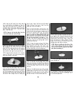
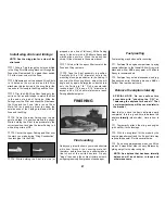
8. Assemble a
12 oz. Great Planes Fuel
Tank
(GPMQ4105) with the
right angled
fuel
pickup tube. The Tank is installed “
sideways”
under the Instrument Panel with the back end
pointing toward the right side of the fuse. Work a
small piece of 1/4” foam rubber above and below
the Tank, then slide a couple of scrap balsa
sticks under the tank to secure it in position and
provide throttle pushrod clearance. We flew all of
our test flights with the tank mounted in this
position and experienced no problems.
❏
9. Mark and drill 1/4” fuel tube holes through
the firewall, being careful not to damage the tank.
Install both the fuel supply and pressure tubes.
For ease of fueling we suggest a
Great Planes
Fuel Filler Valve
(GPMQ4160) that can be
mounted on the cowling during final assembly.
❏
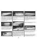
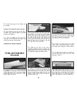
1. Check the fit of the Stab with the Stab
Saddle. Make any adjustments to the Stab
Saddle very carefully, so that you
don’t change
the built-in incidence angle
.
❏
2. Put the stab on the saddle and add a small
weight to hold it in place. Place a 36”
straightedge across the Wing Saddle and clip it
to F-2B. Sight across the top of the Stab to the
straightedge from six to ten feet behind the
model. If both Stab tips are not equidistant
below the straightedge, make
small
adjustments
to the Stab Saddle to correct the problem. Use a
str ing, pinned to the top center of F-2, to
equalize the distance of the Stab tips.
A=A
A
A
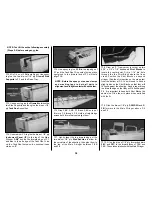
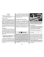
Attach the stab and fin
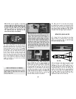
Use scrap 3/16” or 1/4” plywood to make two
servo mounting blocks approximately 3/4”
square. Use epoxy to glue these blocks as
shown above the Fuel Tank Roof so that the
servo horn aligns with the throttle arm on the
engine. Use the same pushrod technique as
described in Step 8 for a direct hookup. The
down-side to this method is that the servo will
not be accessible after sheeting without cutting
into the top of the fuse...but, because servos
are generally quite reliable, this may never
be necessary.
SERVO OPTION FOR 1.20 ENGINE
To simplify the throttle hookup for a 1.20 4-
stroke engine you may want to consider the
following suggestion.
37


