


•
B
B
—
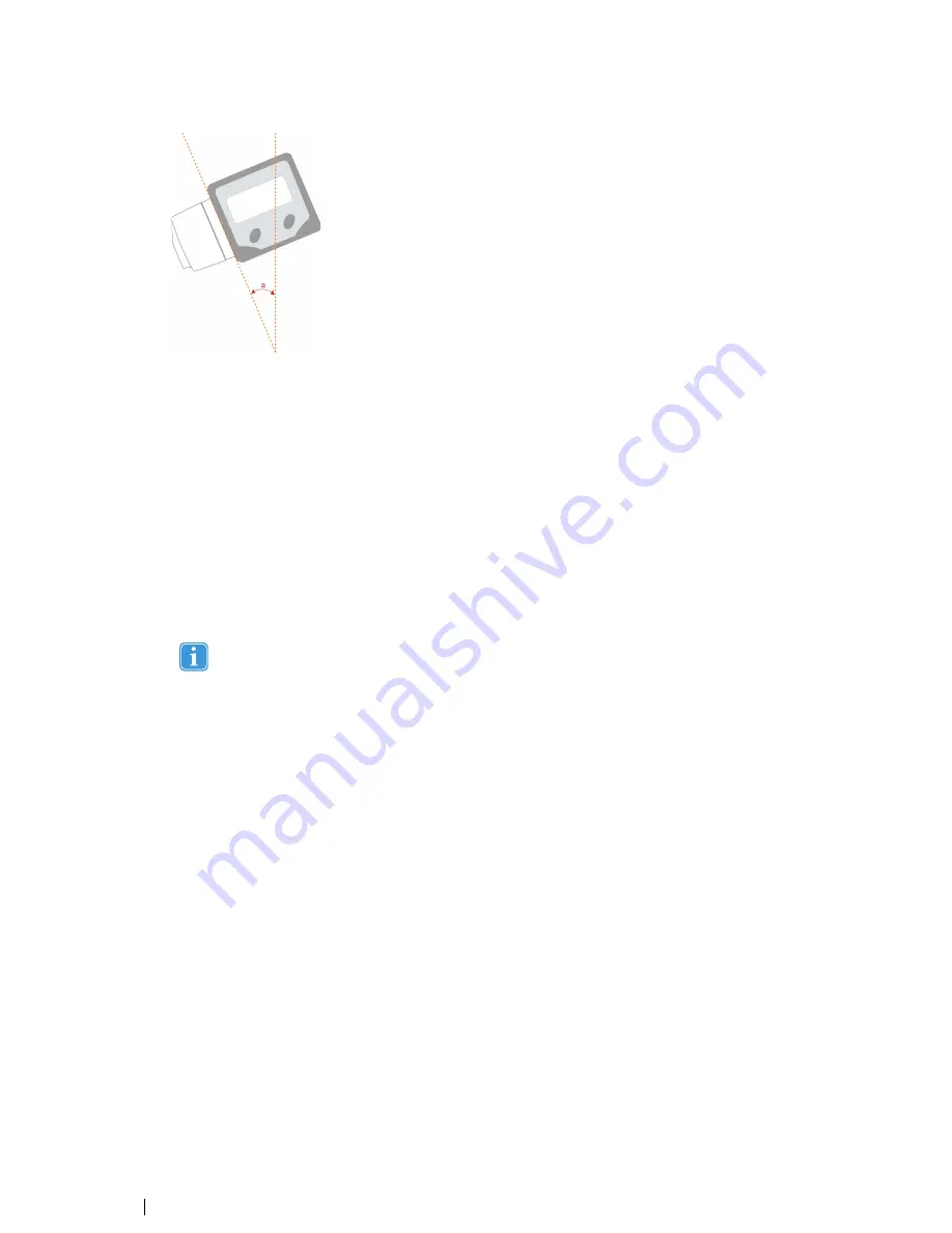
display angle. Measure the angle between the vertical plane and the active display using the digital angle meter.
In a scene camera setup measure the angle between the vertical plane and the calibration grid. If the display is tilted
forward you should enter a negative angle (use
“
-
”
in front of the value). If the active display is completely vertical the
angle value is 0. In a scene camera setup where you want to track objects on a horizontal table the angle would be
90 degrees.
•
C
C
—
Height difference between lowest row of pixels on the display and the measuring point of the eye tracker (read
4.7.1 Reference Measurement Point of the Tobii X2 Eye Tracker, page 15). Measure the height difference between
the measuring point on the eye tracker and the bottom of the active display area. If the active display is located below
the measuring point on the eye tracker (for example, in a projector setup) the value will be negative. Enter the value
in the X Configuration Tool with a
“
-
”
in front to signify it as a negative value.
•
D
D
—
distance between the measuring point of the eye tracker (read
4.7.1 Reference Measurement Point of the Tobii
X2 Eye Tracker, page 15) and the display. Measure the distance from the measuring point on the Tobii X2 Eye Track-
er to the front of the active display on the monitor, projection screen, or TV screen, or in a scene camera setup to the
virtual screen. If the measuring point on the eye tracker is located behind the active display, enter a negative distance
(use
“
-
”
in front of the value).
Always make sure that the distance to the active display is long enough for the eye tracker to track the en-
tire area. Please read section
5 Positioning, page 19.
•
U
Ussee S
Siid
dee O
Offffsseett
—
If the Eye Tracker is not placed right in front of the screen with the axis horizontally aligned, an
offset can be entered in the X Configuration Tool. In this case:
a.
Check the Use Side Offset tick box. The upper right area of the X Configuration Tool window becomes active.
b.
Enter the side offset value, measured from the center of the active display to the center of the eye tracker. Enter
a negative value if the eye tracker is located to the left of the center as seen from the front.
•
U
Ussee R
Roottaattiioonn
—
If the eye tracker is not placed parallel with the display or tracked object:
a.
Check the Use Rotation tick box. The bottom right area of the X Configuration Tool window becomes active.
b.
Enter the value of the angle between the back of the eye tracker and the active display. If the eye tracker is ro-
tated clockwise, enter a negative value.
3.
S
Saavvee tto
o E
Eyyee TTrraacckkeerr
—
Once you have entered all the needed parameters corresponding to your setup, you must click
Save to Eye Tracker in order to start using this configuration. The parameters will then be sent to the eye tracker and the
eye tracker will immediately be properly configured. When you change any parameter value in the tool, the button must
be pressed again for the eye tracker to get the new settings.
4.
You also have the option of saving the configuration as an .xcfg file locally on your computer by clicking the S
Saavvee ttoo
FFiillee...... button and setting the name and location of the file. Click LLooaad
d ffrroom
m F
Fiillee...... to load a previously saved .xcfg config-
uration file. This is useful if you want to save a particular configuration of a setup to be able to reuse it at a later point in
time or from another computer.
18
4 Setting Up the Tobii X2
–
60 Eye Tracker
Tobii X2-60 Eye Tracker User
’
s manual v.1.0.3 - en-US
Содержание X2-60
Страница 1: ...U Us se er r s s M Ma an nu ua all T To ob bi ii i X X2 2 6 60 0 E Ey ye e T Tr ra ac ck ke er r...
Страница 2: ......
Страница 4: ......
Страница 43: ...37...


