


6
4. NOMeNCLATURe ANd FUNCTIONS
3
4
[Front]
[Side]
10
11
8
1
9
2
5
6
7
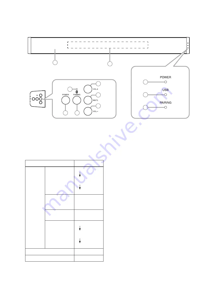
1. Power switch
Hold down this switch for 3 seconds or more to
switch between normal operation and power
standby mode. To turn OFF the AM-CF1, hold
down this switch for over 10 seconds.
2. Power indicator
(blue/blue-green/green/orange/red)
Operating Status
Lighting Status
[When
power is
ON]
Start
processing in
progress
Blue
Flashing
blue-green
Green
Unit
initialization in
progress
Orange
Normal
operation mode Green
Power OFF
processing in
progress
Red
Flashing
blue-green
Blue
Power standby mode
Red
Power OFF
Extinguished
3. Microphone & speaker section
An array microphone and a 2-way stereo speaker
are housed inside the front panel.
4. Multifunction indicator (green/red)
This indicator is housed inside the front panel and
provide 3 different displays using 7 LEDs. Lighting
operations differ depending on the contents being
displayed.
(1) When displaying the microphone input level:
When the AM-CF1 unit is in use at a web
conference, etc., only one LED facing in the
direction of the speaker’s voice lights green.
The LED’s brightness varies depending on
the microphone’s input level and the louder
the input level, the brighter it shines. The LED
remains unlit when the microphone input is
small or the microphone input level display
function is set to OFF.
(2) When the microphone is muted:
When the Mute switch (10) on the side panel is
pressed and the microphone output is muted,
the indicator lights red. Whether a single LED
or an LED bar light can be selected in the web
app settings. (See p. 13.)
(3) When adjusting the output volume:
The indicator lights green when changing the
output volume using the Volume Up (9) or
Down (11) switches located on the side panel.
Current output volume setting status is
displayed. (See p. 15.)
5. USb connection indicator (green/blue)
Lights green when a PC is connected to the PC
USB port (16).
Lights blue after flashing green during unit
initialization.


