Toa AM-CF1 Скачать руководство пользователя страница 13

13

8. SySTeM SeTTINgS

8.1. Overview of System Settings

Connecting the AM-CF1 unit to a PC by way of a LAN cable allows the following function settings and 

maintenance to be performed using the PC’s browser:

[Unit Settings]

•  Network settings

•  Clock settings

•  User account settings

[Operation Settings]

•  Volume adjustment and current value confirmation of various audio inputs and outputs

•  EQ parameter adjustment

•  Settings the range in which the array microphone detects and tracks sound sources

•  Echo and noise cancellation settings

•  Operation settings for general-purpose control input and output

•  Operation setting for the multifunction indicators

•  Saving and reading of the above setting data

[Maintenance Function]

•  Firmware update

8.2. System Requirements

PC hardware requirements are as follows:

Display

1366 x 768 resolution or higher

Confirmed PC operation environments are as follows:

OS

Windows 7, 32-bit

Windows 10, 64-bit

macOS 10.13 High Sierra 

Browser

Google Chrome 63.0.3239.132, Safari 11.0.3

8.3. Connections

 Step 1. Start up the web browser and enter “Unit’s IP address: 8000” in the address field. 


Example: 192.168.14.10: 8000


The login screen is displayed.

Tip: The IP address is factory-preset to “192.168.14.10.”

 Step 2. Enter a user name and a password.


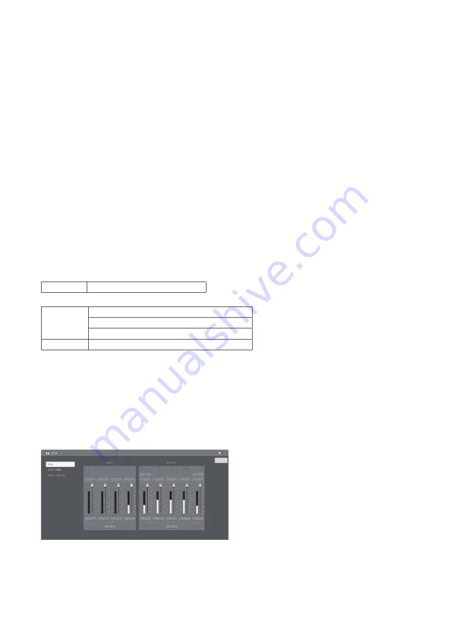
The menu screen is displayed.

Note

Do not launch multiple web browsers at the same time.

Tip

Default user name and password are as follows:

User name: admin

Password:  admin

Содержание AM-CF1

Страница 1: ...rated Audio Collaboration System AM CF1B AM CF1W Thank you for purchasing TOA s Integrated Audio Collaboration System Please carefully follow the instructions in this manual to ensure long trouble fre...

Страница 2: ...7 8 Removable Terminal Plug Connection 12 8 SYSTEM SETTINGS 13 8 1 Overview of System Settings 13 8 2 System Requirements 13 8 3 Connections 13 9 OPERATION 14 9 1 Turning Power ON and OFF 14 9 2 Swit...

Страница 3: ...e the unit is designed for indoor use do not install it outdoors If installed outdoors the aging of parts causes the unit to fall off resulting in personal injury Also when it gets wet with rain there...

Страница 4: ...e that the use of other adapter may cause a fire If dust accumulates on the power supply plug or in the wall AC outlet a fire may result Clean it periodically In addition insert the plug in the wall o...

Страница 5: ...Industry Canada To reduce potential radio interference to other users the antenna type and its gain must be so chosen that the equivalent isotropically radiated power e i r p is not more than that nec...

Страница 6: ...g on the contents being displayed 1 When displaying the microphone input level When the AM CF1 unit is in use at a web conference etc only one LED facing in the direction of the speaker s voice lights...

Страница 7: ...support 10BASE T or 100BASE TX When connecting the PoE extender use the following TPE 117GI made by TRENDnet 15 Power input terminal Connect a 12 V DC power source to this terminal For AC adapters us...

Страница 8: ...o mount the AM CF1 unit to a wall Be sure to use the following wall mounting brackets and screws If hardware other than that mentioned below is used the unit could fall down potentially resulting in d...

Страница 9: ...s removed in Step 1 Note Screws can be installed not only from the upward direction but also from the side or downward direction 7 CONNECTIONS 7 1 AC Adapter Connection Connect the AC adapter 1 to the...

Страница 10: ...emove it straight away from the receptacle Do not pull on the cable to extract the plug as this may damage the connector OK NG Correct insertion direction Do not pull on the cable 7 4 AUX Input Connec...

Страница 11: ...nections Use the supplied removable terminal plug 6 pins for connection Connect the control input and output blocks using 2 control lines from external control devices For removable terminal plug conn...

Страница 12: ...is crushed possibly resulting in an excessive rise in joint temperatures Use cables of AWG 12 24 Terminal plug connections Step 1 Loosen the terminal screw then insert the cable Step 2 Retighten the t...

Страница 13: ...or the multifunction indicators Saving and reading of the above setting data Maintenance Function Firmware update 8 2 System Requirements PC hardware requirements are as follows Display 1366 x 768 res...

Страница 14: ...ion in progress Orange Normal operation mode Green Power OFF processing in progress Red Flashing blue green Blue Power standby mode Red Power OFF Extinguished 9 2 Switching between Power Standby and N...

Страница 15: ...ont panel speaker can be adjusted when in Normal Operation mode While the volume is being adjusted the current output volume setting state is displayed by the front panel mounted multifunction indicat...

Страница 16: ...e C terminal For example when terminals 1 2 have been allocated to Preset Memory Nos 1 2 in the contact input settings shorting individual terminals to the C terminal allows Preset Memory Nos 1 2 to b...

Страница 17: ...Memory 1 2 to terminals The Preset Memory is accessed when its corresponding terminal is shorted to the C terminal If different Preset Memories are assigned to multiple terminals the last shorted term...

Страница 18: ...Hold down the Power switch while confirming that the Power indicator is flashing blue green After approximately 30 seconds the Power indicator will light green and the USB connection indicator will li...

Страница 19: ...che License 2 0 Apache 2 0 The 3 Clause BSD License The 2 Clause BSD License MIT License MIT Others We do not guarantee the operation of open source software itself but we do guarantee the functionali...

Страница 20: ...ble terminal block 6 pins no voltage make contact relay contact output Network I F 10BASE T 100BASE TX RJ 45 Microphone Unidirectional electret condenser type Frequency Characteristics 20 Hz 20 kHz AU...

Отзывы: