W W W . T M G I N D U S T R I A L . C O M
P 0 8 / 4 1
T o l l F r e e : 1 - 8 7 7 - 7 6 1 - 2 8 1 9
INSTALLATION AND
ASSEMBLY
Do not
lift or move unit without appropriately rated
equipment. Be sure the unit is securely attached to lifting
device used.
Do not
lift unit by holding onto arms, carriage or other
non-approved lifting areas.
Never
use the wood shipping skid for mounting the unit.
Choose a safe location that is in compliance with current
work place safety regulations. Failure to properly install
the machine can lead to improper and unsafe operation.
Machine size is approximately:
75” w x 60” l x 28” h
(1905mm w x 1524mm l x 711mm h)
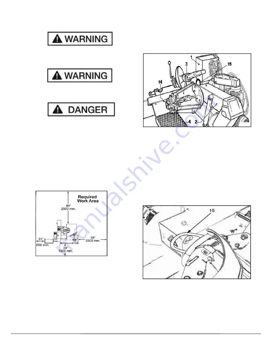
Recommended minimum work area distance from walls
as shown in the diagram.
These measurements are the tire changers working range.
Persons other than specially trained and authorized
operators are expressly forbidden to enter this area.
Transporting / Moving
The tire changer has a lifting ring which has been
positioned specifically for moving the machine.
Before attempting to transport the machine, follow
these instructions:
1) Make sure the horizontal chuck arm (
2
) is completely
lowered.
2) Make sure the chuck jaws (
3
) are closed.
3) Bring the sliding table (
4
) all the way left towards the
horizontal chuck arm.
4) Insert a lifting hook and cable with a minimum lifting
capacity of 1500-pounds (680 kgs.) around the liftingring
(
15
). Make sure the cable is of sufficient length to
properly clear the tire changer when handling.
5) Take precaution to keep track of the cable connecting
the Control Pod while moving the Tire Changer.
6) Lift only with an approved capacity lifting truck or
approved devise that is capable of safely handling the
load.


