


FloppyFlex User Manual Version 2.0 - 22 August 2022
- 27 -
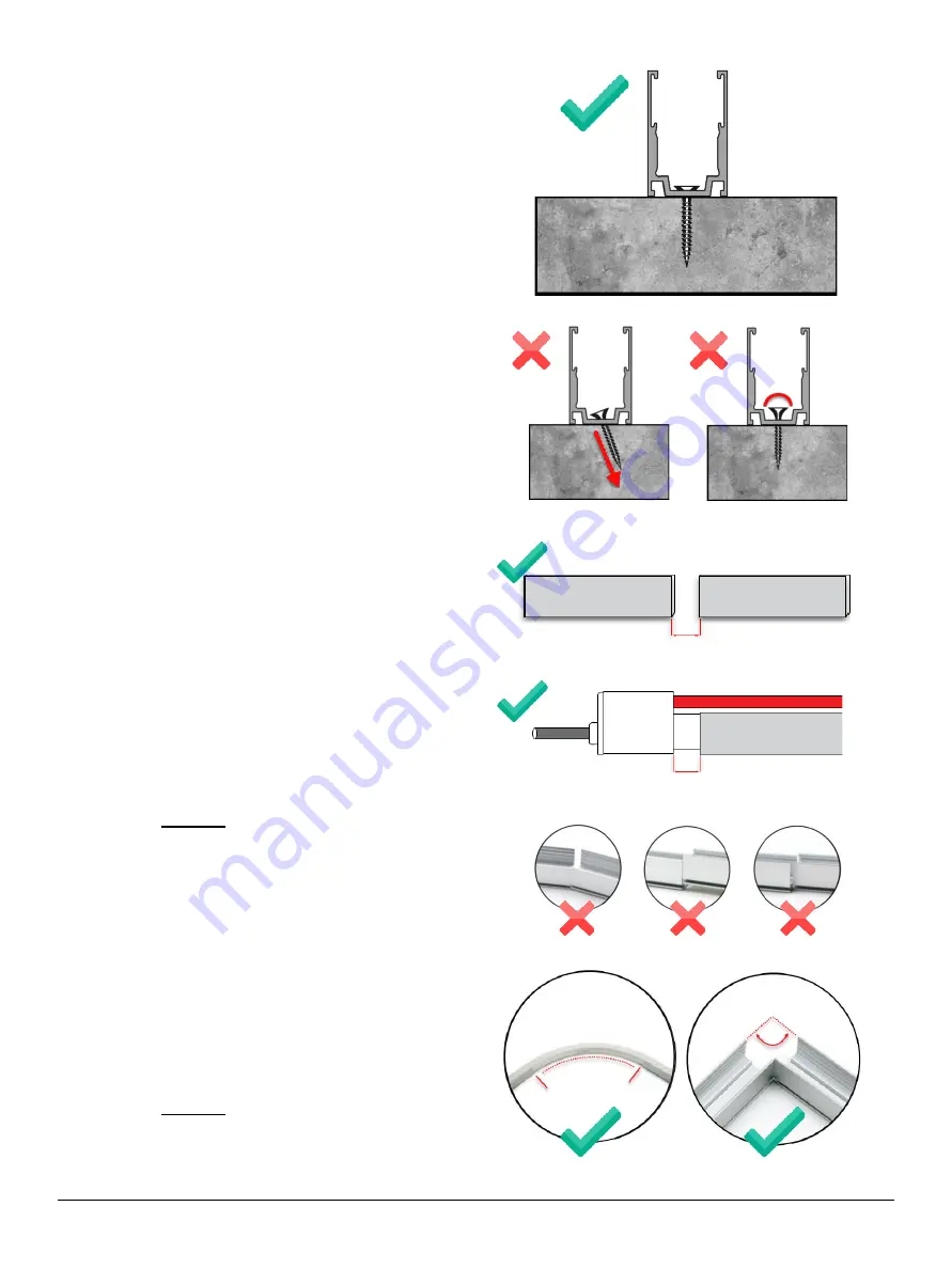
≥5 mm
≥10 mm
•
Screw Positioning and Installation
Profiles have pre-drilled mounting holes to
make installation quick and easy.
When installing the screws into the profile, it
is important to maintain a level and even
force with your screwdriver or electric drill.
Marking and drilling pilot holes smaller than
the diameter of the screw makes the process
easier and reduces the chance of material
blowout.
Follow these guidelines:
o
Avoid installing screws at an angle
.
o
Screws should be installed flush or
lower than the profile base. There
should be no protrusions that disturb
the FloppyFlex body.
o
In cases where the mounting substrate
is rigid, expandable anchors can be
used with screws.
•
Joining Profile Sections
Installing longer FloppyFlex assemblies
sometimes requires multiple sections of
profile installed end-to-end or at various
angles to achieve shapes.
Follow these guidelines:
o
When two lengths of profile are
installed end-to-end, make sure to
leave at least 5mm of space between
the profile ends.10mm space is
recommended between the
FloppyFlex connector and profile end.
Warning
:
Avoid
any
Horizontal,
Parallel, or Angular misalignment
when installing profile end-to-end. This
may cause stress on the FloppyFlex
and damage over time.
o
When two lengths of profile are used
to create a curve, be certain to leave
appropriate spacing with respect to the
FloppyFlex minimum bending
diameter.
o
Profiles can only be installed at right
angles when two separate FloppyFlex
assemblies meet at the ends.
Warning
: Bending a run FloppyFlex at
a right angle violates the minimum
bending diameter and can result in
damage to the FloppyFlex assembly.


