background image


19

172-65443A-01 (CV-COS)  17 Nov 2014


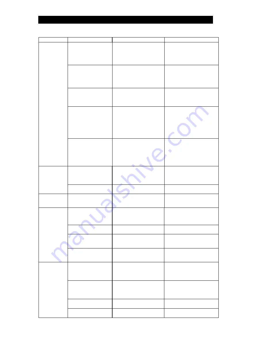
Problem Cause 

Diagnosis 

Remedy 

(Countermeasure)

Air is not being 

supplied to the 

positioner 

Make sure that the 

compressor is operating as 

it should; make sure that 

the regulator connected to 

the positioner inlet is set 

Initiate the supply of the 

designated air supply 

pressure to the positioner 

(Confirm product 

specifications) 

The input signal wiring 

is incorrectly 

connected 

Check to make sure the 

wiring is connected to the 

correct terminals and that 

the + and - polarity is not 

reversed 

Correct the connections 

The input signal is not 

being input 

Check that 4 to 20 mA is 

being input by the 

positioner connection 

terminals 

Repair the operation signal 

origin or repair the signal 

wiring 

Positioner’s internal 

parts are broken   

(the diaphragm is 

cracked, etc.) 

Check to see if any 

unusual noise is coming 

from the positioner 

Replace with a new 

positioner/actuator unit 

[Check to make sure that 

the valve is not operating 

(traveling) too often and 

that the ambient 

temperature is not too high] 

No movement 

at all 

There is water or oil 

inside the positioner 

Check to see if there is 

water or oil entrained in the 

supply air; check to see if 

the humidity at the control 

valve piping location is too 

high 

Replace with a new 

positioner/actuator unit and 

improve the quality of the 

air supply 

There is water or oil 

inside the positioner 

Check to see if there is 

water or oil entrained in the 

air supply 

Replace with a new 

positioner/actuator unit and 

improve the quality of the 

air supply 

Valve opens 

and closes too 

slowly 

The filter regulator is   

clogged 

Check the filter 

Clean the filter or replace 

with a new filter 

Valve travel is 

unstable 

The setting of the 

controller is faulty 

Check the set value based 

on the controller’s PID 

parameters 

Adjust the controller's 

setting values 

There is a build-up of 

dirt on the trap valve 

seat or on the float 

Check the trap valve seat 

and the float 

Clean or replace with a new 

trap valve seat or float 

The body is installed 

tilted 

Check the installation 

conditions 

Correct the installation 

The float is deformed 

Check the float 

Replace with a new float 

(Inspect for water hammer 

or freezing) 

Steam is 

blowing 

There is vibration in 

the piping 

Check the piping 

conditions 

Remove the source of the 

vibration or reinforce the 

piping supports 

The primary pressure 

exceeds the trap valve 

seat maximum 

working pressure 

Check the primary 

pressure 

Change to a suitable 

pressure 

Water is inside the 

float 

Check the float 

Replace with a new float 

(Investigate to see if the 

flow medium contains 

corrosive substances) 

Output piping is 

clogged 

Check the outlet piping 

Clean or modify the piping 

No condensate 

is discharged   

The trap valve seat is 

clogged 

Check the trap valve seat 

Clean or replace with a new 

trap valve seat 


Содержание CV-COS

Страница 1: ...ogawa Hyogo 675 8511 Japan Tel 81 0 79 422 1122 Fax 81 0 79 422 0112 Copyright 2014 by TLV Co Ltd All rights reserved ISO 9001 ISO 14001 Manufacturer Kakogawa Japan is approved by LRQA LTD to ISO 9001 14001 Pneumatic Control Valve with Built in Separator and Steam Trap CV COS ...

Страница 2: ...am Trap is a revolutionary product that combines an integrated positioner diaphragm type actuator with a separator and a steam trap Steam using equipment can achieve its intended efficiency only if the steam being used is very dry Using steam in which matter such as condensate scale or types of grease is entrained can not only result in problems with the steam using equipment and in lowered produc...

Страница 3: ...ates that there is a potential threat of death or serious injury CAUTION Indicates that there is a possibility of injury or equipment product damage DANGER NEVER apply direct heat to the float The float may explode due to increased internal pressure causing accidents leading to serious injury or damage to property and equipment Install properly and DO NOT use this product outside the recommended o...

Страница 4: ...reezing may damage the product leading to fluid discharge which may cause burns or other injury Use only under conditions in which no water hammer will occur The impact of water hammer may damage the product leading to fluid discharge which may cause burns or other injury Make sure the power supply is OFF before carrying out work on the wiring or inspections involving disassembly If such work is c...

Страница 5: ...lve Characteristic Maximum Allowable Temperature TMA Maximum Operating Temperature TMO Maximum allowable pressure PMA and maximum allowable temperature TMA are PRESSURE SHELL DESIGN CONDITIONS NOT OPERATING CONDITIONS Valve No is displayed for products with options This item is omitted from the nameplate when there are no options Nameplate layout depends on product specifications Actuator Pneumati...

Страница 6: ...e Size mm in 15 1 2 20 3 4 25 1 40 11 2 50 2 Maximum Operating Pressure PMO Maximum Operating Temperature TMO See nameplate Applicable Fluid Steam Valve Plug Stem Valve Seat Material Stainless steel Valve Characteristic Equal percentage Stroke Travel 15 mm 9 16 in Rangeability 50 1 Cv US 3 5 6 0 9 0 27 40 Cv UK 2 9 5 0 7 5 23 33 Cv and Kvs Values Kvs DIN 3 0 5 1 7 7 23 34 Valve Leakage Rate Leak R...

Страница 7: ...nge 15 Valve Bonnet Guide 16 Valve Bonnet Guide Gasket 17 Main Body 18 Valve Seat 19 Valve Seat Gasket 20 Separator Screen 21 Separator 22 Wave Spring 23 Trap Body Gasket 24 Guide Pin 25 Bolt 26 Trap Body 27 Float Cover 28 Float 29 Float Cover Bolt 30 Spring Washer 31 Trap Cover Gasket 32 Trap Valve Seat Gasket 33 Trap Valve Seat 34 Bushing 35 Nameplate 36 Trap Cover 37 Trap Cover Bolt 38 Bolt 39 ...

Страница 8: ...to make sure that the piping where the product is to be installed is constructed properly If the piping is not correctly constructed the valve may not perform optimally 1 Blowdown Before installing the CV COS unit be sure to blow down all piping thoroughly If this is not possible perform a blowdown using the bypass valve Blowdown is especially important for newly installed piping or after the syst...

Страница 9: ...utlet Pipe For ease of maintenance installation of a union connection is recommended for the trap outlet pipe Connect the outlet pipe to a condensate return line or extend it to a trench In the case of the latter make sure the end of the pipe is above the waterline Dirt and water may be sucked up by the vacuum formed during trap closu Approx 300 400 400 100 0 0 1 0 0 1 0 0 1 0 0 1 0 1 1 0 1 1 100 ...

Страница 10: ...y installation of the If air quality results in operation failure the entire actuator unit including the there is a problem in operation determine the cause using the Troubleshooting section in this manual Avoid Foreign Matter and Water Hammer impact from wate Piping G Be careful that the piping gaskets do not protrude outside the inner bore of the flange order to select a gasket of Air Line Blowd...

Страница 11: ...screwdriver into the notch 4 in the terminal plug 3 and remove the terminal plug 3 from the plug connector case 2 4 Insert the input signal wiring through the wiring connection port 6 and connect the wiring to the 1 2 and ground terminals at the symbols imprinted on the terminal plug 3 taking care not to reverse the polarity 5 Reinsert the connected terminal plug 3 into the plug connector case 2 W...

Страница 12: ...ot 0 MPaG 0 psig refer to the Adjusting the Zero Span section of this product Instruction Manual and adjust the zero 6 Set the controller operation signal to 100 20 mA 7 Check the CV COS valve travel and the actuator air supply pressure Valve Travel Fully open valve travel 100 Air Pressure Approximately 0 38 MPaG 54 psig check the pressure gauge on the pneumatic positioner for the air pressure NOT...

Страница 13: ...on signal to 4 1 mA 1 and check to make sure the valve begins to open 8 Change the operation signal to 4 mA 0 and check to make sure the valve is completely closed the actuator pressure gauge is completely at zero 9 Change the operation signal to 20 mA 100 and make sure that the stroke indicator reads in the vicinity of 100 If it does not use a precision flat head screwdriver to turn the span adju...

Страница 14: ... the zero span if that does not solve the problem replace with a new valve plug stem and valve seat Leakage from gland area Visual inspection is fluid leaking from the gap between the gland and the valve stem or are there signs it has leaked previously Coat the gland and the valve stem with grease if that does not solve the problem replace with new V rings Air leakage from actuator Visual inspecti...

Страница 15: ... an operation signal of 4 to 20 mA Removing Reattaching the Stem Bracket Plates Part During Disassembly During Reassembly Set the actuator air supply pressure to 0 MPaG 0 psig to maintain the valve in the fully closed position Set the actuator air supply pressure to 0 MPaG 0 psig to maintain the valve in the fully closed position Check to make sure the valve stem and actuator stem are in firm cont...

Страница 16: ... anti seize Valve Bonnet Guide Pull up and off taking care not to damage the valve plug stem or valve seat The difference between the inner diameter of the body and the outer diameter of the valve bonnet guide is very small so make sure that it does not tilt and get caught when pulling the valve bonnet guide up and off Take care not to damage the valve plug stem or valve seat The difference betwee...

Страница 17: ...t Remove with a socket wrench Consult the table of tightening torques and tighten to the proper torque Trap Valve Seat Gasket Remove the gasket Replace with a new gasket if warped or damaged Trap Cover Gasket Remove the gasket Replace with a new gasket if warped or damaged Float Cover Bolt Spring Washer Float Cover Float Float Cover Gasket Trap Valve Seat Trap Valve Seat Gasket Trap Cover Bolt Dis...

Страница 18: ...st Across Flats mm in Torque N m lbf ft Dist Across Flats mm in Bolts and Nuts for Stem Bracket Plates 7 5 1 8 5 16 7 5 1 8 5 16 7 5 1 8 5 16 7 5 1 8 5 16 7 5 1 8 5 16 Guide Bushing Valve Bonnet Section 120 88 24 15 16 120 88 24 15 16 120 88 24 15 16 120 88 24 15 16 120 88 24 15 16 Bolts for Flange 40 29 17 21 32 40 29 17 21 32 40 29 17 21 32 40 29 17 21 32 50 37 19 3 4 Valve Seat 100 73 30 13 16 ...

Страница 19: ...tem up and down and check to see if it catches Reassemble the valve bonnet section correctly Valve Leakage There is a problem with the sealing surfaces of the valve plug and valve seat Check the valve plug and valve seat Replace with a new valve plug stem and valve seat The bellowphragm in the actuator is broken Check to see if a large amount of air is leaking from the exhaust tap Replace with a n...

Страница 20: ... quality of the air supply There is water or oil inside the positioner Check to see if there is water or oil entrained in the air supply Replace with a new positioner actuator unit and improve the quality of the air supply Valve opens and closes too slowly The filter regulator is clogged Check the filter Clean the filter or replace with a new filter Valve travel is unstable The setting of the cont...

Страница 21: ...the instructions contained in the TLV Instruction Manual for the Product Duration Of Warranty This warranty is effective for a period of the earlier of i three 3 years after delivery of Products to the first end user in the case of sealed SST Series Products for use in steam pressure service up to 650 psig ii two 2 years after delivery of Products to the first end user in the case of PowerTrap uni...

Страница 22: ... WHERE DUE TO OPERATION OF LAW CONSEQUENTIAL AND INCIDENTAL DAMAGES UNDER THIS WARRANTY UNDER ANY OTHER EXPRESS WARRANTY NOT NEGATED HEREBY OR UNDER ANY IMPLIED WARRANTY NOT NEGATED HEREBY INCLUDING THE IMPLIED WARRANTIES OF MERCHANTABILITY AND FITNESS FOR A PARTICULAR PURPOSE CANNOT BE EXCLUDED SUCH DAMAGES ARE EXPRESSLY LIMITED IN AMOUNT TO THE PURCHASE PRICE OF THE DEFECTIVE PRODUCT THIS EXCLUS...

Страница 23: ...ividual specification requirements so please verify your particular product Body Options Section A Standard Flangeless No Plug With Plug 1 N m 10 kg cm Torque N m lbf ft Dist Across Flats mm in 30 22 12 Rc PT 3 8 BSPT3 8 NPT3 8 NOTE Wrap sealing tape 3 3 5 times around the threaded portions Applications for Use Where there are large amounts of dirt or scale or for applications such as heating in w...

Страница 24: ...tor Manual Condensate Discharge Rc PT 1 4 BSPT1 4 NPT1 4 Rc PT 1 4 BSPT1 4 NPT1 4 Integrated Filter 5 m Integrated Filter 5 m 0 3 m With Filter Regulator Automatic Condensate Discharge With Filter Regulator Mist Separator Automatic Condensate Discharge Rc PT 1 4 BSPT1 4 NPT1 4 Rc PT 1 4 BSPT1 4 NPT1 4 Integrated Filter 5 m Integrated Filter 5 m 0 3 m ...

Отзывы: