Our Brands:
FlinQ | iProtect | Park Assist | ParkEyes | Siqura | VDG
Installations in over 80 countries
TKH Security B.V. | +31 182 592 333 | [email protected] | tkhsecurity.com
Meridiaan 32
2801 DA, Gouda
The Netherlands
PD900/PD910/PD920
January 4, 2021
Installation ManualPD900/PD910/PD920
Page 18
Zero Downtime Power (ZDT) Switching (selected models)
If you connect the DC 12V power jack and PoE at the same time, the power input will come from the
DC 12V connector.
If the DC 12V power source fails, the camera will seamlessly switch power input to the RJ-45
port, until the DC 12V power source is restored.
3.2 Connect Ethernet cable
For Ethernet cable connection, follow these steps:
1. Connect one end of the Ethernet cable to the RJ-45 connector of the camera.
2. Plug the other end of the cable to the network switch or PC.
3. Check the status of the power and the network activity indicator LEDs. If a LED is unlit,
check the corresponding connection.
•
The green link LED is lit when there is a good network connection.
•
The orange network LED flashes to indicate that there is network activity.
3.3 Connect Audio/Alarm I/O and RS-485
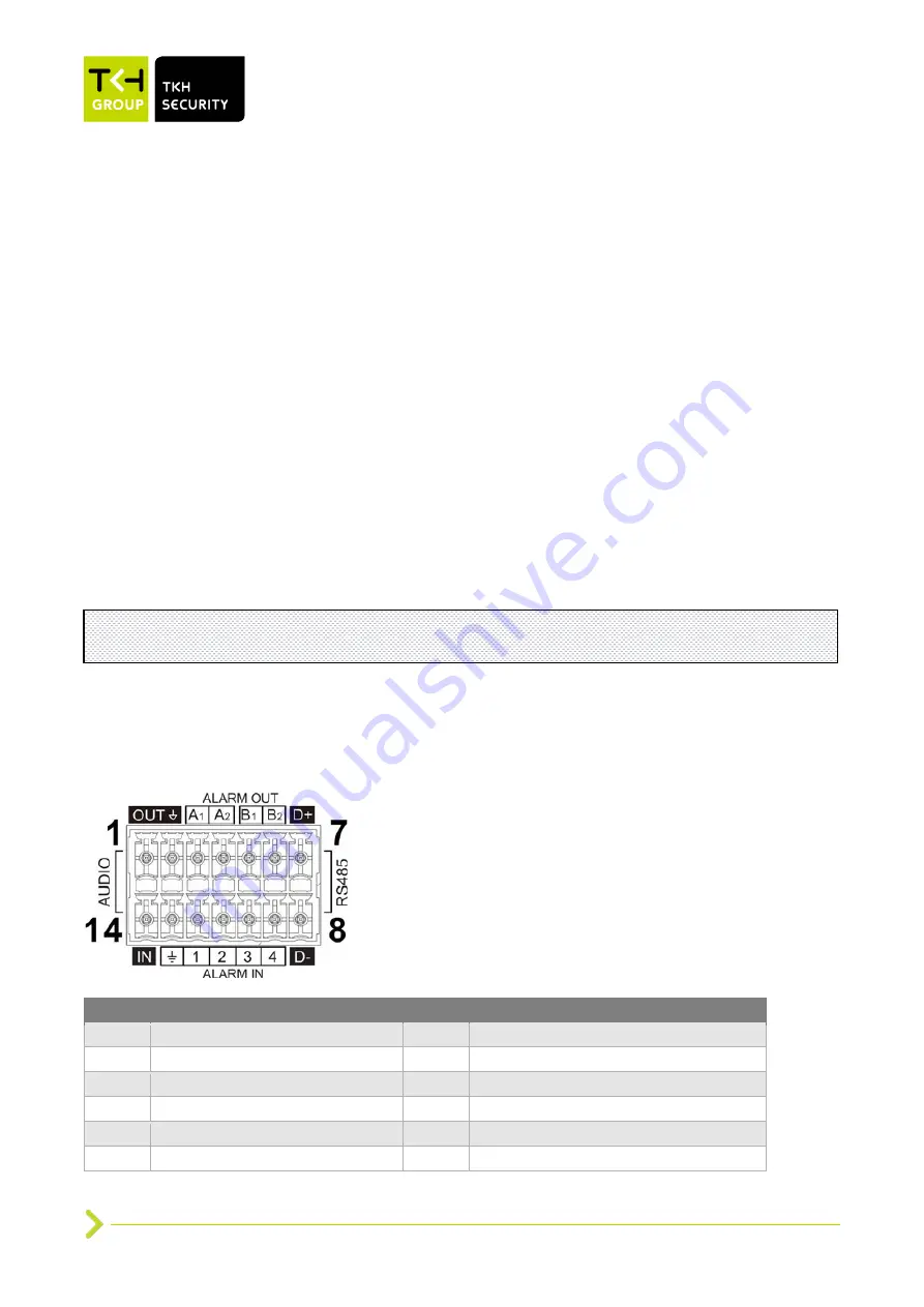
See the diagram and pin definitions below for audio/alarm I/O and RS-485 connection.
Pin
Definition
Pin
Definition
1
Audio OUT
8
RS-485 D-
2
GND (Audio I/O)
9
Alarm IN 4
3
Alarm OUT A1
10
Alarm IN 3
4
Alarm OUT A2
11
Alarm IN 2
5
Alarm OUT B1
12
Alarm IN 1
6
Alarm OUT B2
13
GND (Alarm I/O and RS-485)
Note
: In some cases, Ethernet crossover cable may be needed when connecting the camera
directly to the PC.


