Page 28
For technical questions, please call 1-888-380-0318.
Item 64806
Sa
FE
ty
W
E
lding
t
ip
S
tig
/ Stick
control
S
Wir
E
M
aint
E
nanc
E
Duty Cycle (Duration of Use)
avoid damage to the Welder by not welding for more
than the prescribed duty cycle time.
The Duty Cycle
defines the number of minutes, within a 10 minute
period, during which a given welder can produce a
particular welding current without overheating.
For example, a welder with a 40% duty cycle at
90 A welding current must be allowed to rest for at least
6 minutes after every 4 minutes of continuous welding.
Failure to carefully observe duty cycle limitations
can easily over-stress a welder’s power generation
system contributing to premature welder failure.
This Welder has an internal thermal protection system to
help prevent this sort of over-stress. When the Welder
overheats, it automatically shuts down. Should this
occur, rest the TIG Torch or Electrode Holder on an
electrically non-conductive, heat-proof surface, such
as a concrete slab, well clear of the ground clamp.
allow the Welder to cool with the power Switch on,
so that the internal Fan will help cool the Welder.
When normal operation resumes,
use shorter welding periods and
longer rest periods to prevent needless wear.
tig rated duty cycles
Stick rated duty cycles
120 VAC
40% Use at 90A
For 10 continuous Minutes
240 VAC
15% Use at 200A
For 10 continuous Minutes
120 VAC
40% Use at 70A
For 10 continuous Minutes
240 VAC
15% Use at 170A
For 10 continuous Minutes
4
Minutes
Welding
6
Minutes
resting
1-1/2
Minutes
Welding
8-1/2
Minutes
resting
4
Minutes
Welding
6
Minutes
resting
1-1/2
Minutes
Welding
8-1/2
Minutes
resting
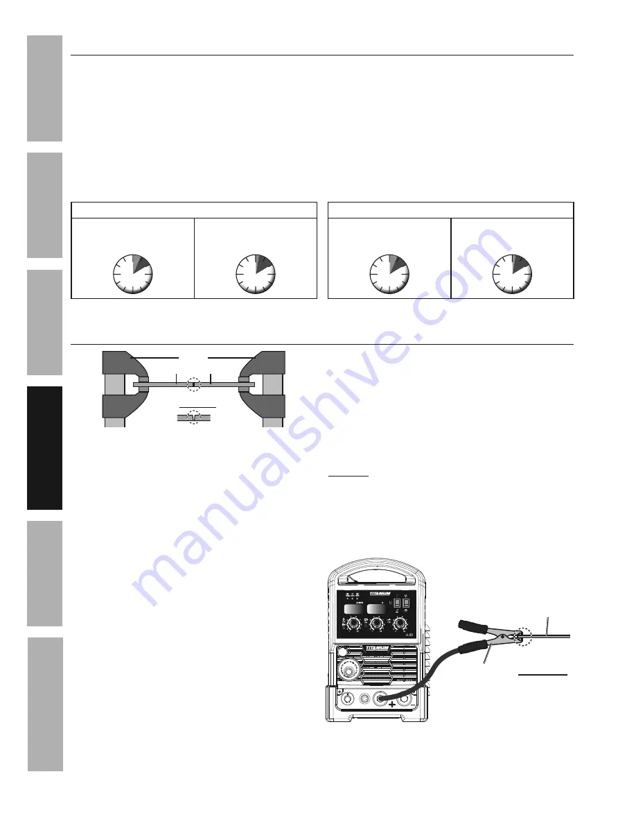
Setting up the Weld
clamps
workpieces
chamfer thick workpieces.
clean surfaces
to bare metal.
1.
Make practice welds on pieces of scrap the
same thickness as your intended workpiece
to practice technique before welding anything
of value.
Clean the weld surfaces thoroughly
with a wire brush or angle grinder; there
must be no rust, paint, oil, or other materials
on the weld surfaces, only bare metal.
2. Use clamps (not included) to hold the workpieces
in position so that you can concentrate on
proper welding technique. The distance (if any)
between the two workpieces must be controlled
properly to allow the weld to hold both sides
securely while allowing the weld to penetrate fully
into the joint. The edges of thicker workpieces
may need to be chamfered (or beveled)
to allow proper weld penetration.
noticE:
When welding equipment on a vehicle,
disconnect the vehicle battery power from both the
positive connection and the ground before welding.
This prevents damage to some vehicle electrical
systems and electronics due to the high voltage
and high frequency bursts common in welding.
3. Clamp Ground Cable to bare metal on the
workpiece near the weld area, or to metal work
bench where the workpiece is clamped.
ground connection depends
on desired welding polarity
Workpiece
ground
clamp
clean
surface to
bare metal.


