41
Mechanical Considerations
1.
Where possible, allow 6" spacing between injector mounting plates.
2.
The ProPAC-3 will arrive with the AC power wiring pre-wired by Titan. The 18" leads for AC
power is the only wiring provided. No electrical conduit, seal-off, or junction box is provided.
3.
The additive line-feeding additive to the injectors must be large enough to provide the minimum
volume of additive for all injectors operating simultaneously. It is recommended the additive pump and
motor, and the additive feed lines be sized for 200% of maximum flow required.
4.
Any restriction in the additive feed line reducing maximum required flow will cause the injectors
to alarm indicating an additive flow problem. Example: Required minimum additive feed to injectors is 5.0
gpm and an Oval Gear Meter is in the additive feed line downstream of the discharge of the pump. The
Oval Gear Meter will only allow 2.8 gpm of additive flow, consequently, the injectors will alarm.
5.
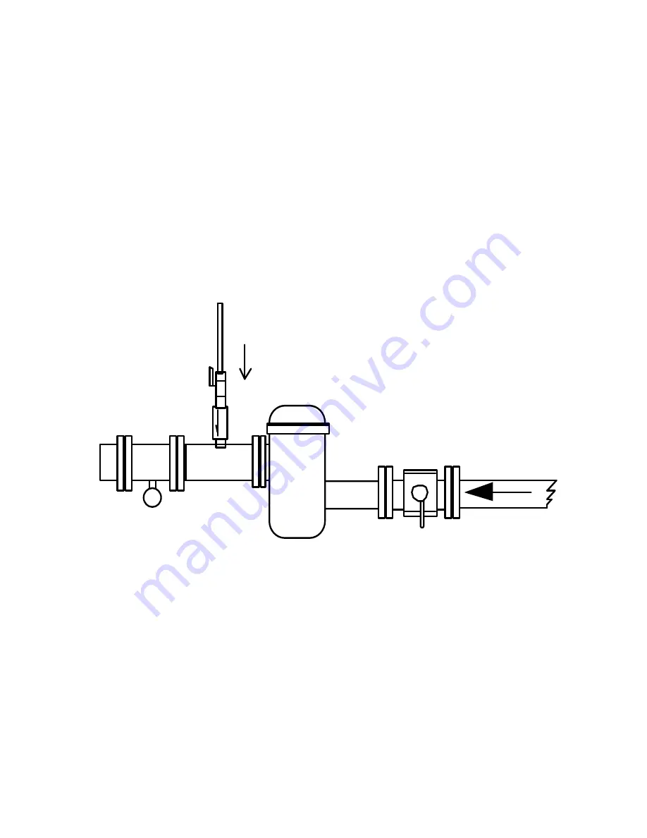
At the additive injection point, for each injector, it is absolutely necessary that a check valve and
a ball valve be installed. Do not rely on the injector check valve alone to prevent product flow. It is highly
possible a leaking check valve will allow product under pressure to flow through the ProPAC-3 in a reverse
direction. The solenoid control valve is not designed to prevent flow in a reverse direction. Product flow
through the injector flow meter will cause the injector to alarm indicating a Leak Alarm.
Strainer
PRODUCT
Check
Ball Valve
Additive
Flow
6.
In order for additive to inject into a product line, the additive pressure at the point of injection
must be a minimum of 25 psig above the product pressure (differential pressure). The additive pump and
the additive motor must be size correctly in order to provide the minimum pressure differential and additive
flow rate required. Typical additive pump pressures average approximately 150 psig, however, each site
requires individual considerations.
7.
The installation should provide adequate additive pump pressure to the injector for the entire
load. It has been noted, at some locations, it is possible the additive pump/motor are turned OFF as the last
gallon of product is loaded. If the injection rate is high and residual additive pressure is insufficient, the last
injection may not be completed, thereby, initiating an alarm. It may be practical to install a time delay relay,
thereby, extending the time before the additive pump/motor is turned OFF at the end of a product load.
8.
Install the ProPAC-3 where the graphical display is at normal eye level. This level will enhance
the viewing angle of the graphical display and make servicing easier to perform.
Содержание ProPAC-3
Страница 39: ...39 ...


