3515 Flex-Wing Rotary Cutter
48
Titan Implement, LLC
February 2020
(423) 334-0012
9.6.3 Blade Sharpening
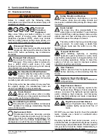
CAUTION
Sharp Object Hazard
The grinder may catch on the blade during
sharpening, propelling it forcefully. To
prevent the possibility of serious injury, make sure
blades are secured against movement while
sharpening.
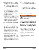
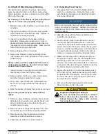
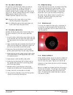
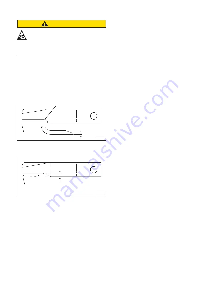
When sharpening blades, always sharpen both blades
at the same time and grind the same amount on each
blade to maintain balance. Unbalanced blades will
cause excessive vibration, which can damage gearbox
bearings. Vibration may also cause structural cracks
to the rotary cutter. Follow the original sharpening
pattern. Do not sharpen blades to a razor edge; leave
a 1/16” blunt edge. Do not sharpen the back side of
the blade. Do not heat and pound out the edge.
1/16”
FOLLOW ORIGINAL PATTERN
MAINTAIN
CORNER
TI-00064
Replace the blades when worn more than 1/2” from the
original edge. Always replace blades in pairs.
ORIGINAL
BLADE EDGE
1/2” MAXIMUM
TI-00063
9.7 Blade Carrier Removal
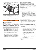
1. Remove the cotter pin and loosen the castle nut on
the gearbox shaft. Do not remove the nut until the
blade carrier is loosened.
2. Use a suitable two jaw gear puller to pull the carrier
off the tapered gearbox shaft.
3. If a gear puller is not available, insert a bar through
the blade bolt access the hole with the end against
the blade carrier. Strike the opposite end of the bar
sharply. Rotate the blade carrier 180 degrees and
repeat until the carrier breaks loose.
4. Remove the castle nut and the blade carrier.
9.8 Blade Carrier Installation
1. Clean the splines on both the blade carrier and the
output shaft.
2. Position the carrier on the gearbox output shaft and
install the castle nut. Tighten the nut to a minimum
450 ft. lbs.
3. Strike the carrier near the hub several times with
a heavy hammer to seat the hub. Use care not to
strike the nut or the end of the shaft.
4. Retighten the nut to 700 ft. lbs.
5. Install the cotter pin and spread the tangs.
9.9 Slip Clutch Operational Check
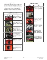
The rotary cutter is equipped with three slip clutches,
with one located in front of each spindle gearbox. The
slip clutches serve as overall protection for the tractor,
driveline, and gearboxes. Even though new clutch
assemblies are “run-in” and checked for torque prior
to shipment, readjustment may be advisable if the
clutch has been exposed to weather for an extended
period of time. The clutch facing and plates should be
inspected for rust and/or corrosion. After the rotary
cutter has been stored for thirty days or more, perform
the following check:
1. Make a trial run in the heaviest operating conditions
expected. If any clutch slips noticeably, tighten the
eight adjusting bolts no more than 1/2 turn between
trial runs until the clutch slippage is reduced.
2. Scribe a mark across the clutch facing of each
slip clutch. When subjected to shock loads, a
separation of the marks will assure that the clutch
setting is correct.
Note:
Check the clutches periodically during the first
hour of operation for excessive heat build-up
due to unexpected slippage.
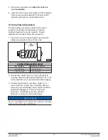
If a clutch is being rebuilt (new facing and/or plates),
it is necessary to “run-in” these parts prior to final
adjustment. The plates should be thoroughly cleaned
and free of foreign material, as well as being checked
for warping with a straight edge. Warped plates cannot
be adjusted properly and will not hold. To accomplish
the “run-in” after assembly, follow this procedure:
1. Tighten all the adjusting bolts evenly until the clutch
cannot be slipped by hand.
2. With the blade carrier locked in a stationary position,
operate with the PTO at idling speed (approximately
100 RPM), until evidence of heating is noted.
Do
not allow the clutch to overheat.
Содержание 3515
Страница 1: ......
Страница 2: ......
Страница 4: ......
Страница 6: ......
Страница 55: ...Titan Implement LLC 55 3515 Flex Wing Rotary Cutter 423 334 0012 February 2020 ...
Страница 59: ...Titan Implement LLC 59 3515 Flex Wing Rotary Cutter 423 334 0012 February 2020 ...
Страница 61: ...Titan Implement LLC 61 3515 Flex Wing Rotary Cutter 423 334 0012 February 2020 ...
Страница 63: ...Titan Implement LLC 63 3515 Flex Wing Rotary Cutter 423 334 0012 February 2020 ...
Страница 64: ...3515 Flex Wing Rotary Cutter 64 Titan Implement LLC February 2020 423 334 0012 12 4 Wheel Lift ...
Страница 65: ...Titan Implement LLC 65 3515 Flex Wing Rotary Cutter 423 334 0012 February 2020 ...
Страница 67: ...Titan Implement LLC 67 3515 Flex Wing Rotary Cutter 423 334 0012 February 2020 12 6 Driveline Shield ...
Страница 70: ...3515 Flex Wing Rotary Cutter 70 Titan Implement LLC February 2020 423 334 0012 12 9 Outboard Gearbox ...
Страница 71: ...Titan Implement LLC 71 3515 Flex Wing Rotary Cutter 423 334 0012 February 2020 12 10 1 540 RPM Driveline ...
Страница 72: ...3515 Flex Wing Rotary Cutter 72 Titan Implement LLC February 2020 423 334 0012 12 10 2 1000 RPM Driveline ...
Страница 73: ...Titan Implement LLC 73 3515 Flex Wing Rotary Cutter 423 334 0012 February 2020 12 10 3 Center Deck Driveline ...
Страница 74: ...3515 Flex Wing Rotary Cutter 74 Titan Implement LLC February 2020 423 334 0012 12 10 4 Wing Deck Driveline ...
Страница 75: ...Titan Implement LLC 75 3515 Flex Wing Rotary Cutter 423 334 0012 February 2020 12 11 Wing Deck Driveline ...
Страница 76: ...3515 Flex Wing Rotary Cutter 76 Titan Implement LLC February 2020 423 334 0012 ...
Страница 77: ...Titan Implement LLC 77 3515 Flex Wing Rotary Cutter 423 334 0012 February 2020 ...
Страница 78: ...Form No 3515M Printed in USA 09 2016 ...

