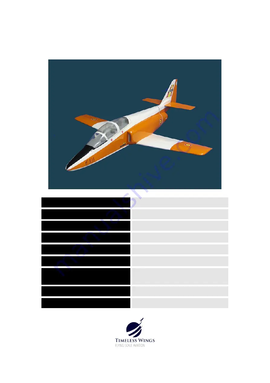
Timeless Wings CASA C-101 AVIOJET Скачать руководство пользователя страница 1

1

CASA C–101 AVIOJET

CONSTRUCTION MANUAL Version 2.1

SCALE

APPROX 1:13.5

WING SPAN

31 INCHES

WEIGHT

22.5 OZS

WING AREA

170 SQ INS

WING AIRFOIL

SELIG 3021

WING LOADING

19 OZS/SQ FT

FAN

50MM (e.g. Dr Mad Thrust 50mm, XRP-

50mm,WeMoTec 50mm)

CELLS

3S – 4S LiPo1000mAh - 1300mAh

POWER required

180W +

Содержание CASA C-101 AVIOJET

Страница 1: ...rsion 2 1 SCALE APPROX 1 13 5 WING SPAN 31 INCHES WEIGHT 22 5 OZS WING AREA 170 SQ INS WING AIRFOIL SELIG 3021 WING LOADING 19 OZS SQ FT FAN 50MM e g Dr Mad Thrust 50mm XRP 50mm WeMoTec 50mm CELLS 3S...

Страница 2: ...ble but will require a longer drying time This model is optimised around 50mm fans with brushless motors and power input of 180W and up There are very many photographs of the full size CASA Aviojet on...

Страница 3: ...FORWARD FUSELAGE CONSTRUCTION Glue two F14 FWD LONGERONS on top of FUSELAGE FLOOR Insert F1 and F2 in place on FUSELAGE FORMER F13 Insert F3 into F13 then glue all formers to the FUSELAGE FLOOR and F1...

Страница 4: ...4 Glue F6A to FRONT of F6 Assemble F4 F5 F6 and F15 in place as shown in the photograph below and when aligned correctly glue in position...

Страница 5: ...uct walls as shown in the photograph below Using a sharp blade and a steel rule trim to the border ___________________________________________________________________ Place the trimmed duct outer wall...

Страница 6: ...____________________________________________ Using 80 grit sandpaper roughen the ducting where the surfaces mate then glue together with a good quality plastics glue that is designed for PETG We use a...

Страница 7: ...6 to allow the ducting to slide into position so there is a similar amount protruding front and back Glue in position with UHU All Plastics glue or similar Note the inboard edge of the ducting sits fl...

Страница 8: ...8 Use masking tape to form a dam on the front face of F6 then fill the void between the former and the duct with epoxy or flexible filler Any residual void at the back of F5 may be filled now too...

Страница 9: ...nt of F5 and flush or a few mm protruding from the rear of F6 You may need the following tools MID FUSELAGE CONSTRUCTION F22 is temporarily attached centrally to the underside of the Fuselage Floor wi...

Страница 10: ...Laminate F9 as shown the spring clips are useful holding the assembly in position until the glue dries The balsa parts go to the front important Place F7 F8 and F9 in position on F22 Do not glue just...

Страница 11: ...________________________________________________________ FT1 needs to be slightly modified before it can be used a 30mm wide tab needs to be added centrally to the front end as shown in the before and...

Страница 12: ...art ___________________________________________________________________________ Glue the two parts F16 to both sides of the fuselage assembly as shown below only gluing the areas where the flat parts...

Страница 13: ...F22 between F8 F9 remains trimmed flush with the front of F8 Laminate the WING BOLT PLATE WB1 from the three pieces then fit the 4mm blind nut by giving a gentle tap into the hole with a hammer Glue i...

Страница 14: ...__________________________________________________________________ Each side of the forward fuselage is now sheeted with 1 5mm balsa Trace the shape required with a piece of paper first using a separa...

Страница 15: ...ed the AIR INTAKES AI 1 2 3 4 can be laminated two per side fitted into position then shaped The lower section of F7 is removed to allow for wing positioning The fuselage so far should look like below...

Страница 16: ...ructure to the front of FT6 and formers F17 and F18 as shown Laminate F10 to F10A then glue in place as shown ply side may be forward or rearward it doesn t matter which Glue F11 in place then F20 Tur...

Страница 17: ...e of the elevator Sand the whole tailplane elevator assembly to shape then hinge using CA hinges Referring to the side view on the plans cut a small section out of FT5 to allow movement of the elevato...

Страница 18: ...icker piece of piano wire threaded through the formers to drill through the F21 assembly leaving a path for the sleeve which is now glued in place See the photographs later in this manual showing the...

Страница 19: ...f the full size to assist Glue TAILPIPE RING TP1 in position at the rear of F12 then glue F9B to the front of the rear fuselage assembly Note that the slots for the ply FUSELAGE JOINERS may need to be...

Страница 20: ...os that are now available Holes in the ribs for the servo leads have not been cut These can be done using a sharpened piece of brass tubing before assembly begins or using a Dremel tool after the ribs...

Страница 21: ...ness at the trailing edge before shaping is thus 4 5mm Align the assemblies as shown below and glue in place noting that glue is not applied to the section of ribs in front of the spar at this stage G...

Страница 22: ...S1 DO NOT GLUE at this stage Prepare the starboard wing lower surface sheeting in the same manner as the centre section sheeting then glue WING TE RHS in place on top of the sheeting Mark out the posi...

Страница 23: ...oting that once again the parts of the ribs forward of the spar are not glued at this stage PVA glue is most suitable for this task Glue ROOT RIB R1 in position followed by the WING FALSE LEADING EDGE...

Страница 24: ...with 1 5mm balsa making provision for the aileron extension leads to be routed through the centre section sheet Laminate the WING TIPS WT1 then glue in position along with CS4 NOTE CS4 in the kit is...

Страница 25: ...at the control throws are close to that specified on the plans and that the Centre of Gravity is not behind the position shown on the plans The model has been flown with a CG ranging from the plans po...

Страница 26: ...s applies to all makes of fan The shroud outer diameter becomes about 55 5mm after the tape The tailpipe overlaps 6mm forward from the rear of the fan shroud Once in position the 18mm of fan shroud th...

Страница 27: ...27...

Страница 28: ...provided The Tailpipe is glued along the seam with cyano and reinforced by clear packing tape which is also used to attach it to the fan or use good quality masking tape If additional tailpipes are re...

Страница 29: ...immediately after launch Grip the model behind the wing near where the fuselage splits and with full power applied take a few steps forward launching the model in a level or slightly nose up attitude...

Страница 30: ...s perfect here There is no wing drop at the stall if the model has been built straight there is no washout in the wing nor is it necessary With its viceless handling good looks and exhilarating perfor...

Отзывы: