TierTime UP300 Скачать руководство пользователя страница 50

50

Back to Directory

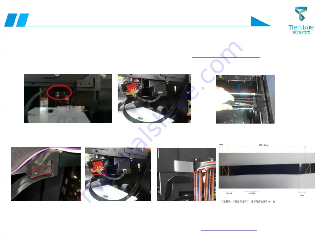
Operation Guide 15- Method of replacing FFC-Y axis cable and Y-axis 

limit

Tools

Cross screwdriver, 2.5mm hex wrench

1. First remove the aluminum column, the rear plate and the right side plate with a hex wrench;

Method of removing the shell

2. Use a cross screwdriver to remove the two screws fastening the Y-axis adapter board;
3. Gently remove the adapter board and unplug the Y-axis limit cable on the adapter board;
4. Use the pliers to gently pull the Y-axis limit in the direction shown, and the Y-axis limit can be removed. 
(You can change the Y-axis limit here)

5. Remove the internal injection molded part shown in the figure with a cross screwdriver;
6. Slowly remove the adapter board, open the connector, and take out the FFC cable; pay attention to the folding of the cable.

Note: 1. Reciprocating folding will damage FFC cable easily, so it is best 
to mark and complete folding in one time.
2. Pay attention to the installation direction of the FFC cable during 
installation. The metal side corresponds to the metal side of the interface.

Y-axis folding method

Back to Directory

Содержание UP300

Страница 1: ...UP 300 Service Manual 1 UP 300 Service Manual...

Страница 2: ...Fi Wi Fi transmission failed 09 Failed to connect UP 300 Wi Fi 10 Failed to register an account no activation email received 11 nozzle calibration alignment failed 12 The nozzle does not extrude fila...

Страница 3: ...cally 24 No model or support in a certain height range the model does not match the original image 25 The surface quality of the model is poor the surface has abnormal texture 26 Print platform contin...

Страница 4: ...aligning cable and platform adapter board 07 Method of replacing Wire interior lights 08 Method of replacing Wire door inspection cable 09 Replacing front door magnet 10 Method of replacing nozzle FF...

Страница 5: ...4 Method of replacing X axis light bar 25 Method of replacing X axis limit 26 Method of replacing Y axis belt 27 Method of replacing Y axis motor 28 Method of replacing Y axis light bar assembly 29 Me...

Страница 6: ...replace Z limit Do not break off the limit with hands if it can t touch Limit wire motor wire broken plug loose needle retreated Turn off the power remove the rear panel and check if the limit on mai...

Страница 7: ...Turn off the power check if the motor wiring of the fault axis is damaged and if the plug is broken if not remove the mainboard and check if the motor wire is broken or if the plug is loose Turn off t...

Страница 8: ...ntact is poor Turn off the power and replace the nozzle adapter board Turn off the power and replace the mainboard adapter board Turn off the power and check if the FFC cable of the nozzle has defects...

Страница 9: ...too tight Remove and replace Y motor Replace Y axis light bar X axis light bar abnormal sound Turn off the power manually pull the Y axis and check if the X axis has obvious blackening or axial scrat...

Страница 10: ...ny operation Buzzer display damaged Turn off the power remove the display and replace the buzzer components on the display Remove and replace display Mainboard damaged Turn off the power and replace t...

Страница 11: ...liquefied gas Turn off the power and replace the nozzle assembly Remove and replace the nozzle assembly Remove and replace the nozzle plate Remove and replace the integrated liquefied gas It is recom...

Страница 12: ...ive location software installation directory Software version problem Download the latest control software from the designated official website http www tiertime com https www up3d com PC mainboard is...

Страница 13: ...sufficient wireless signal strength wireless signal instable Restart UP 300 and the software and reconnect Reconfigure wireless settings Replace a more stable and stronger wireless signal Software ver...

Страница 14: ...me needs to be distinguished from other Wi Fis Insufficient wireless signal strength wireless signal instable Restart the router Restart UP BOX and the software and reconnect Reconfigure wireless sett...

Страница 15: ...l address but the activation email has not been received Intercepted as spam Check the spam and restore the email Software version problem Download the latest control software from the designated offi...

Страница 16: ...ning Height aligning cable damaged Unplug the height aligning cable connecting the height aligning assembly Replace the height aligning cable Short circuit or damage to height aligning PCB board Remov...

Страница 17: ...amaged and replace if yes Check the nozzle FFC cable for damage if replace if yes Remove and replace the nozzle FFC cable Remove and replace the nozzle CFC cable nozzle nozzle plate nozzle motor tempe...

Страница 18: ...oad the latest control software from the designated official website connect to the network and activate CPU http www tiertime com https www up3d com Error when CPU is activated failed to return activ...

Страница 19: ...int the model being transferred Remove the cover of the wire box and check if the remaining filament in the box is about to run out Software material weight setting is improper Set the actual weight o...

Страница 20: ...ed and some areas are outside the molding space Set to automatically place and retransfer the model in the software Model size out of molding range In the software if you select the model with the lef...

Страница 21: ...transfer is completed you can see that the platform starts to heat up slowly Wait for 15 minutes to let the nozzle warm up and start printing If you do not need to warm up the platform before printin...

Страница 22: ...LED light is on Motor cable of fault axis is broken plug is loose Turn off the power remove the rear panel and check if the motor wire of the fault axis is broken if not re plug the motor plug of the...

Страница 23: ...error Please close the front door of the printer The front door is not closed properly Check if the front door is closed normally Disconnect during transferring data file to UP 300 Ensure that the con...

Страница 24: ...if the platform FFC cable of the heating base plate is broken 26P cable Remove and replace the platform FFC heating cable Remove and replace 26P cable Heating aluminium substrate damaged Turn off the...

Страница 25: ...nozzle nozzle plate nozzle motor temperature control components etc Large stratification fast printing speed insufficient nozzle motor power Turn off the power remove and replace the nozzle board Turn...

Страница 26: ...and re initialize push the Y axis back and forth to check if the X axis motor pulley and the connecting rod pulley have glue failure Turn off the power and re initialize hold the nozzle and nozzle hol...

Страница 27: ...fast Choose Normal or Better print speed Platform temperature is not enough when the print task starts Warm up the platform for a while before transferring the print task When transferring the model s...

Страница 28: ...rmally Front door outer wide component magnet off Front door outer wide assembly deformed Replace the front door or the magnet The wire is used up the wire inspection function is normally turned on Re...

Страница 29: ...ile while the connection is stable Improper print parameter settings Set a small support area and support angle recommended to guide the user re transfer the print model Software problem Completely de...

Страница 30: ...or nozzle damage Turn off the power and replace the nozzle Remove and replace the nozzle Inconsistent nozzle feeding intermittent feeding Turn off the power and replace the integrated liquefied gas T...

Страница 31: ...amaged and if the platform FFC cable of the heating base plate is broken or loose If yes replace the FFC cable re plug Remove and replace the platform FFC cable Heating plate damaged Turn off the powe...

Страница 32: ...vious surface crush scratches etc Remove and replace display Screen signal cable power cable plug loose damaged Turn off the power check whether the signal cable and power cable are damaged whether th...

Страница 33: ...connection is broken Replace with a good USB cable Peripheral interface board damaged Turn off the power and replace the peripheral interface board Remove and replace the peripheral interface board S...

Страница 34: ...lt are loose If yes replace accordingly Failure 1 Failure 2 Failure 3 Failure 4 Limit cable of fault axis is broken plug is loose Check if the fault axis limit limit switch side is damaged broken and...

Страница 35: ...sembly 3 Loosen the 6 screws marked by the red circles in Fig 3 and then remove the right panel assembly 4 Loosen the 2 screws marked in Fig 4 and then pull the upper panel assembly back to the right...

Страница 36: ...ull out the cable plug on the mainboard adapter board 3 Use a cross screwdriver to remove the four screws on the mainboard adapter board 4 Remove and replace the mainboard adapter board Note For the i...

Страница 37: ...screwdriver 2 5mm hex wrench 1 Use a cross screwdriver to remove the 4 screws of the adapter board cover and then remove the rear nozzle cover 2 Pull out the 2 lines as shown in the figure 3 Pull out...

Страница 38: ...two screws fixed on the aluminum substrate 2 Pull out the interface shown in the figure from the bottom to remove the height aligning board component 3 Remove the screws fixing the height aligning boa...

Страница 39: ...onent by removing the CFC cable on the steering gear board 3 Replace the steering gear CFC cable loosen the 4 screws of the adapter board cover and then remove the steering gear CFC cable Note Pay att...

Страница 40: ...latform and pull out the FFC platform cable 4 Use a cross screwdriver to remove the two screws that connect the platform adapter board to the platform 5 Replace the corresponding wire or platform adap...

Страница 41: ...Loosen the 4 screws and remove the rear panel 2 Cut off the cable tie of the interior light wire and then pull out the plug of the interior light in the mainboard Back to Directory cable buckle 1 Loos...

Страница 42: ...mainboard adapter board socket 2 Open the front door loosen the 2 screws of the door inspection fixing block and then remove the fixing block 3 Cut off the 2 cable ties of the machine s internal door...

Страница 43: ...4 screws that attach the front door on the door hinge and then remove the front door assembly 2 Remove 12 round rubber pads then remove 12 screws and remove the front door frame 3 Loosen the 2 screws...

Страница 44: ...cable 3 Unscrew the four screws of the nozzle cover behind the nozzle holder 4 Pull out the interface of the FFC nozzle cable on the PCB nozzle adapter board to remove the nozzle FFC FFC cable foldin...

Страница 45: ...wrench 1 Withdraw the wire and remove the nozzle wire cover 2 After removing the nozzle cable cover pull out the CFC nozzle cable as shown in the figure 3 After removing the fixing screw at the lower...

Страница 46: ...lean the wire feed roller and the wire feed channel Back to Directory Note 1 Remove the nozzle cover by hand do not use excessive force to avoid affecting the nozzle height 2 When installing the nozzl...

Страница 47: ...nal and heating element terminal on the nozzle board and then replace the nozzle PCB board 5 Use a hex wrench to remove the two screws fastening the heat sink This also removes the heating element Alw...

Страница 48: ...Use a hex wrench to remove the screw fastening the nozzle board 4 Then remove the motor wire terminal and heating element terminal on the nozzle board and then replace the nozzle PCB board 5 Use a hex...

Страница 49: ...he rear panel with a 3mm hex wrench and remove the rear panel 2 Find the PCB board that needs to be replaced pull out the wire in the board and then loosen the screw for replacement Note Operators sho...

Страница 50: ...liers to gently pull the Y axis limit in the direction shown and the Y axis limit can be removed You can change the Y axis limit here 5 Remove the internal injection molded part shown in the figure wi...

Страница 51: ...mark with a 2 5mm hex wrench the screw has the grounding wire on the adapter board Tools Cross screwdriver 2 5mm hex wrench 4 Gently remove the adapter board unplug all the plugs on the adapter board...

Страница 52: ...rewdriver to loosen the 2 screws on the filter cover and then remove the cover 2 Pull out the filter element and replace it Pay attention to the direction of the filter element when replacing Back to...

Страница 53: ...mainboard 3 Loosen the 8 screws of the back shield and remove the back shield 4 Loosen the 4 screws that attach the filter assembly to the frame then place the platform to the bottom and remove the f...

Страница 54: ...FFC platform cable from the aluminum substrate interface here you can also replace the FFC platform cable and then loosen the four leveling nuts to remove the aluminum substrate assembly 4 Loosen the...

Страница 55: ...nspection cable loosen the crimping plate slightly and then unplug the wire inspection cable 3 Open the wire box cover and then loosen the 2 screws to pull out the wire inspection assembly 4 Loosen th...

Страница 56: ...xis motor cable and disconnect the X axis motor cable plug from the mainboard blue 3 Remove the four screws that fasten the X axis motor assembly At this time remove the X axis motor unit When install...

Страница 57: ...ponding pulley of the connecting rod and then put the left and right X axis belts on the pulley on the left and right ends of the connecting rod Note that the belt synchronization at the left and righ...

Страница 58: ...bracket assembly and remove the pulley bracket assembly The pulley on the right requires special tooling 3 Pull out the belt stuck in the X bearing sleeve in the direction shown in the figure and the...

Страница 59: ...the pulley bracket 2 Take out the X axis belts on both sides from the X bearing sleeve in the direction as shown 3 Tilt the Y axis connecting rod assembly as shown in the figure so that the X axis lig...

Страница 60: ...unplug the corresponding plugs of Z axis motor cable and X axis limit cable on the mainboard 3 Use a cross screwdriver to remove the X axis limit screw and peel off the black sleeve and then remove t...

Страница 61: ...steering gear and then take out the Y axis belt stuck in the nozzle base in the direction shown 2 Remove the four screws that fasten the Y axis motor with a hex wrench loosening the screw near the fra...

Страница 62: ...rew the two screws in the direction of the rack you need to move the X axis so that the screws are aligned with the holes in the rack 4 Then remove the Y axis motor 1 First remove the rear panel and t...

Страница 63: ...g the shell 2 Remove the four screws of the Y axis nozzle cover with a cross screwdriver pull out the interface of the FFC nozzle cable at the PCB nozzle adapter board and then remove the FFC nozzle 3...

Страница 64: ...he figure 7 Tilt the Y axis connecting rod assembly as shown in the figure so that the X axis light bar at one end is outside the machine body At this time the X axis light bar can be taken out from t...

Страница 65: ...e the Y axis connecting rod assembly can be removed Note When installing pay attention to pressing the wire between the belt and the injection molded part Self test push the Y axis by hand the X axis...

Страница 66: ...able with pliers unplug the Z axis motor cable from the mainboard unwind the winding tube that wraps the Z axis motor cable 3 Remove the 8 screws that lock the rear shield and remove the front shield...

Страница 67: ...rews should be tightened by half a turn alternately to avoid uneven force and then move up and down to ensure smoothness 4 Pull the Z axis to the highest point first tighten the remaining diagonal scr...

Страница 68: ...panel 3 Cut off the cable tie of the Z axis limit cable and then unplug it from the mainboard 4 Place the machine on the side then loosen the 2 screws that lock the limit frame from the bottom and th...

Страница 69: ...the plug connecting the 26p cable to the mainboard adapter board Tool 2 5mm hex wrench 3 Inside the machine unplug the interface of the 26P cable inserted in the platform adapter board and pull it ou...

Страница 70: ...Hex wrench pliers cable tie 4 Cut off the cable tie of the screen power cable and signal cable and remove it from the display panel for replacement 5 As shown below unplug the 2 USB disk interface cab...

Страница 71: ...in the 4 holes marked on the right to release the aluminum column Back to Directory Tools Hex wrench cross screwdriver 3 On the back of the aluminum column loosen the two screws that lock the display...

Страница 72: ...isplay for replacement Replacement of the new display requires 0 5mm thick gaskets Attach gaskets 6 Loosen the fixing screws to remove the wifi component then remove the wifi cable for replacement Whe...

Отзывы: