


COMMANDER
TOOLBOX
Software
©
Tieline Technology
- 48 -
August 2002
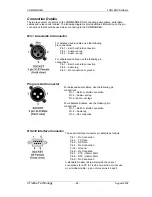
Connection Details
There are several connectors on the COMMANDER for connecting audio cables, serial data
cables and relay control cables. The following diagrams provide detailed information on the pin
connections that should be used when connecting to the COMMANDER.
Mic / Line Audio In Connector
Program Out Connector
RS 232 Interface Connector
For balanced audio cables, use the following
pin connections.
Pin 1 – Earth or shield connection
Pin 2 – Audio +ve leg
Pin 3 – Audio –ve leg
For unbalanced cables, use the following pin
connections.
Pin 1 – Earth or shield connection
Pin 2 – Audio leg
Pin 3 – No connection or ground
For balanced audio cables, use the following pin
connections.
Pin 1 – Earth or shield connection
Pin 2 – Audio +vet leg
Pin 3 –audio –vet legs
For unbalanced cables, use the following pin
connections.
Pin 1 – Earth or shield connection
Pin 2 – Audio leg
Pin 3 – No connection
The serial interface connector pin detail is as follows.
Pin 1 – No Connection
Pin 2 – TX Data
Pin 3 – RX Data
Pin 4 – No Connection
Pin 5 – Ground
Pin 6 – No Connetion
Pin 7 – CTS / (Alarm Dial)
Pin 8 – RTS / (Alarm Dial)
Pin 9 – No Connection
A standard modem cable will provide the correct
connections for a PC to TieLine connection. Do not use
a null modem cable i.e. do not cross wires 2 and 3.