Rev
L
Jun
202
1
Page 11
Chapter 4 Operation
stage and controller information on start up. See the handbook supplied with the
stepper motor controller for further information.
8) Click ‘Exit’ to sut down the APTConfig utility.
9) Start the APTUser utility - Start/Programs/Thorlabs/APT User/APT User.
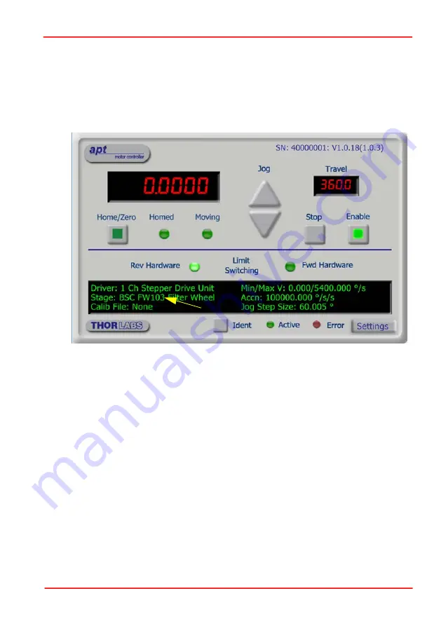
10)The APT server reads in the stage and controller information on boot up and the
settings made above are displayed in the ‘Setting’ window as shown in Fig. 4.4.
Fig. 4.4 APTUser GUI screen
See the APTConfig and APTUser online help files for further information on the use
of these utilities.
4.3 Parameters
The procedure detailed in Section 4.2. loads default parameter values for the filter
wheel. To maximise performance, some tuning of these values may be necessary.
‘Maximum Speed’ and ‘Acceleration’ settings can be adjusted using the ‘Settings’
button on the GUI panel. If the inertia of the loaded filter wheel is too large for a given
acceleration or speed setting, then the wheel will stall. A stall can be detected audibly
or visually, or it can be detected through the APT software. The ‘FWD Hardware’ LED
in the GUI panel is connected to a Hall effect switch within the filter wheel. Six small
magnets are fitted to the rotating wheel, which only operate the Hall switch when the
wheel is at a correct position.


