background image

Page 8

FW103 Motorized Filter Wheel

4.2  Selecting the Stage Type

To ensure that a particular stage is driven properly by the system, a number of parameters

must first be set. These parameters relate to the physical characteristics of the stage being

driven (e.g. min and max positions, leadscrew pitch, homing direction etc.). 
To assist in setting these parameters correctly, it is possible to associate a specific stage

type and axis with the motor controller channel. Once this association has been made, the

server automatically applies suitable default parameter values on boot up of the software.

4.2.1 Using Kinesis Software

1) Install the electronic hardware and connect the controllers to the relevant axes of

the associated stages (see the handbooks for the associated controller).

2) For each Stepper Motor Controller in your system, fit the interlock plug (supplied)

to the MOTOR CONTROL connector on the rear panel.

3) Ensure that the device is connected to the PC and powered up.
4) Run the Kinesis software - Start/All Programs/Thorlabs/Kinesis/Kinesis.
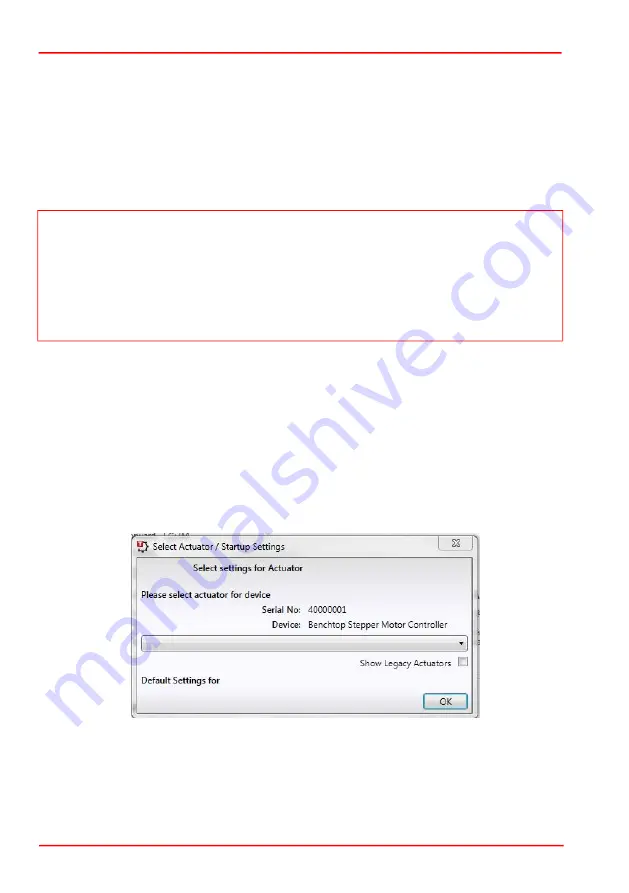
5) On  start-up,  the  'Actuator/Startup  Settings'  window  is  displayed.  This  window

allows the correct actuator to be selected.

Fig. 4.1   Select Actuator Settings Window - 1

Note

To ensure correct operation, it is important to select the correct stage and axis type 

as described above.  If using a BSC20x series controller, proceed as follows. If using a 

KST101 controller, select the stage type via the settings menu on the hardware unit, see 

the handbook for the KST101 for more details.
Selecting an incompatible stage/axis type could result in reduced velocity and/or 

resolution.

Содержание FW103 Series

Страница 1: ...HA0179T FW103 Series Motorized Filter Wheel User Guide Original Instructions ...

Страница 2: ... 2 Mounting 3 3 2 1 General 3 3 3 Connecting The Motor Driver 4 3 4 Fitting the Filters 5 3 5 Transportation 6 Chaper 4 Operation 7 4 1 General 7 4 2 Selecting the Stage Type 8 4 2 1 Using Kinesis Software 8 4 2 2 Using the APT Software 10 4 2 3 Parameters 11 Appendices Appendix A Specifications 12 Appendix B Motor Pin Out Details 13 Appendix C Regulatory 14 Appendix D Thorlabs Worldwide Contacts ...

Страница 3: ...he optomechanical setup within which it sits Choice of electronic controller for the FW103 depends on the required speed of operation The FW103H kit includes the FW103 filter wheel and our BSC201 single channel controller for applications requiring high speed switching 50ms between adjacent filters Where slower speed filter switching is desired 250ms the filter wheel can be driven by our KST101 K ...

Страница 4: ...k of Electrical Shock Given when there is a risk of injury from electrical shock Warning Given when there is a risk of injury to users Caution Given when there is a risk of damage to the product Note Clarification of an instruction or additional information Warnings If this equipment is used in a manner not specified by the manufacturer the protection provided by the equipment may be impaired In p...

Страница 5: ...input and output ports of the filter wheel housing as shown in Fig 3 1 below Fig 3 1 Typical Arrangements The housing contains four 8 32 M4 tapped holes to allow post mounting of the wheel Fig 3 2 Post Mounting Note Retain the packing in which the unit was shipped for use in future transportation Caution Once removed from its packaging the filter wheel is easily damaged by mishandling Handle with ...

Страница 6: ...on cable is not required and the driver should be connected directly to the filter wheel Fig 3 4 KST101 rear panel Caution It is recommended that the FW103 filter wheel is driven by either the Thorlabs KST101 K Cube stepper motor driver or the BSC201 benchtop stepper motor controller If the wheel is being driven by any other driver or controller consult Section B 1 for motor pin out details and Ap...

Страница 7: ...d Securing Screws 2 Each filter sits in a recess which ensures correct positioning Fit the filter into its recess as shown in Fig 3 6 below ensuring that the open end of the filter housing is towards the base plate and the filter is uppermost Fig 3 6 Filter Fitted in its Recess Caution The filters can be damaged or impaired by dirt and grease During the following procedure handle the filters only ...

Страница 8: ...rs are recommended e g Thorlabs part SM1S01 or SM1S3M to ensure secure fitting within the filter recesses Fig 3 7 Filter Retaining Ring and Screws 4 Refit the cover 3 5 Transportation Caution Use only screws of the length specified above Using longer screws will foul the rotation of the wheel Do not allow attachment screws to protrude through the wheel Caution When packing the unit for shipping us...

Страница 9: ...ended that the FW103 filter wheel is driven by either the Thorlabs KST101 K Cube stepper motor driver or the BSC201 benchtop stepper motor controller If the wheel is being driven by any other driver or controller consult Section B 1 for motor pin out details and Appendix B for details of the motor specification Warning The controller must be switched OFF before the stages are plugged in or unplugg...

Страница 10: ... of the associated stages see the handbooks for the associated controller 2 For each Stepper Motor Controller in your system fit the interlock plug supplied to the MOTOR CONTROL connector on the rear panel 3 Ensure that the device is connected to the PC and powered up 4 Run the Kinesis software Start All Programs Thorlabs Kinesis Kinesis 5 On start up the Actuator Startup Settings window is displa...

Страница 11: ... handbook for the associated controller for more information on driving the actuator stage Note To ensure correct operation it is important to select the correct stage and axis type If using a BSC20x series controller select the HS BSC FW103 option If using a KST101 controller select the HS TST FW103 option If using a legacy BSC0xx or BSC10x controller or a TST001 K Cube driver choose the option w...

Страница 12: ...r type from the list displayed e g HS BSC FW103 6 Click the Add Stage Association button 7 The FW103 Filter Wheel and driver unit serial number are added to the list in the main window as shown in Fig 4 3 A default configuration is set at the factory and stored in the non volatile memory of the motor controller The server reads in the Note To ensure correct operation it is important to select the ...

Страница 13: ...ion on the use of these utilities 4 3 Parameters The procedure detailed in Section 4 2 loads default parameter values for the filter wheel To maximise performance some tuning of these values may be necessary Maximum Speed and Acceleration settings can be adjusted using the Settings button on the GUI panel If the inertia of the loaded filter wheel is too large for a given acceleration or speed sett...

Страница 14: ... 20 C to 40 C Motor Specification Only Transition Time Between Filters BSC201 Controller 55 to 60ms KST101 Driver 250ms Motor Specifications Step Angle 1 8 50 poles 2 phases for 360 200 steps Step Accuracy 5 Rated Phase Current 1 A Phase Resistance 4 6 Phase Inductance 10 6 mH Holding Torque 23 1 N cm Detent Torque 1 7 N cm ...

Страница 15: ...type connector which provides connection to the motor controller The pin functions are detailed in Fig B 1 Fig B 1 Motor Connector Pin Out Details Pin Description Pin Description 1 Limit Switch Ground 9 2 Not Connected 10 5V DC 3 C W Limit Switch 11 4 Phase B ve 12 5 Phase B ve 13 5V DC 6 Phase A ve 14 7 Phase A ve 15 Ground Earth 8 5 10 11 15 6 1 ...

Страница 16: ...rmful interference when the equipment is operated in a commercial environment This equipment generates uses and can radiate radio frequency energy and if not installed and used in accordance with the instruction manual may cause harmful interference to radio communications Operation of this equipment in a residential area is likely to cause harmful interference in which case the user will be requi...

Страница 17: ...Page 15 FW103 Motorized Filter Wheel C 2 CE Certificate ...

Страница 18: ...ght were sold to and are currently owned by a company or institute within the EC and are not dissembled or contaminated Contact Thorlabs for more information Waste treatment is your own responsibility End of life units must be returned to Thorlabs or handed to a company specializing in waste recovery Do not dispose of the unit in a litter bin or at a public waste disposal site USA Canada and South...

Страница 19: ...www thorlabs com ...

Отзывы: