© 2011 Thorlabs
34
Thorlabs Beam 4.0
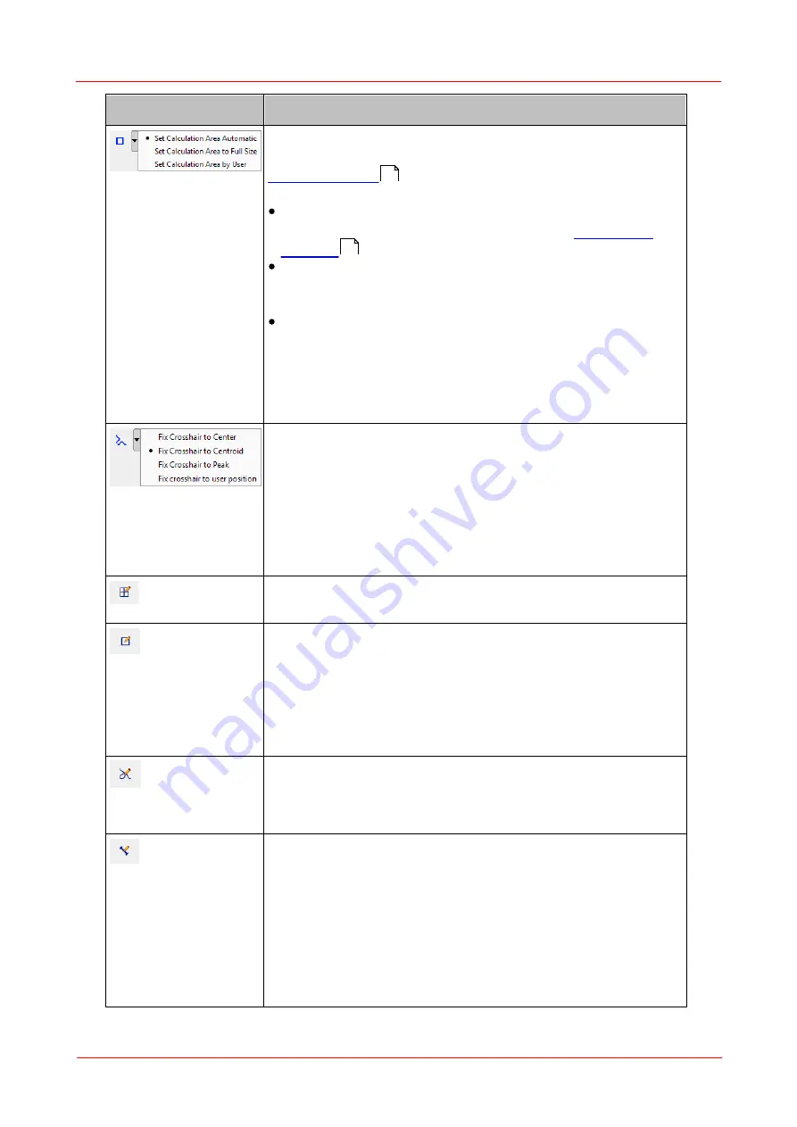
Toolbar Icon
Associated Action
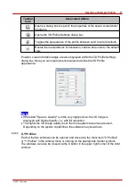
Defines the Calculation Area which is a subarea of the
visible camera image which is itself defined by the ROI (see
). Only pixels within this Calculation Area
are interrogated and recognized for beam data calculation.
Set calculation area automatic:
The software calculates
the area for each new camera image, see
. This is also the default setting.
Set calculation area to full size:
The calculation area
spans the whole image ROI. Note that the Calculation
Area is set to "full size" as soon as a new ROI is set.
Set calculation area by user:
the last user defined
calculation area is used. If no calculation area was defined
or the calculation area is outside the current image roi, a
error message occurs and calculation area returns to the
last selection.The calculation area can be set with the
calculation area edit mode.
Draws X and Y Profiles into the 2D graph displaying the
power distribution within a horizontal and a vertical cross
section.
The positions of these X and Y cross sections can be
defined by either intensity peak, centroid, image center or a
user defined position. By default
'Fix cross hair to
centroid'
is selected. If no user position is defined by the
editor, the user position is the centroid.
Reference
Position Editor
Set a user defined reference position with a click with the
left mouse button inside the projection image.
Calculation
Area Editor
You are expected to draw a rectangle of the desired size
onto the 2D Graph thereafter. Press the left mouse button at
the upper left corner and drag the yellow rectangle into the
image. It should be large enough to cover the desired beam
spot. Release the mouse button at the lower right corner.
Press and hold the right mouse button to move the drawn
rectangle over the display area.
Profile Cross
Editor
To select a user defined position simply click left onto the
image position. The selected pixel row will be the source for
the diagram in the X Profile windows and the selected
column for the diagram in the Y Profile window.
Distance Editor The distance measurement editor opens a table beside the
projection image. When drawing lines into the projection
image, the distance is inserted into the table. A maximum of
10 distances can be drawn. Remove a distance entry by
selecting the entry and pressing the "DEL" key or select the
entry and choose the "Delete Distance" entry from the
context menu.
50
59
Содержание BC106-UV
Страница 1: ...2011 Operation Manual Thorlabs Beam Beam Analyzing Software BC106 VIS BC106 UV ...
Страница 2: ...Version Date 4 0 11 04 2011 2011Thorlabs 2011Thorlabs ...
Страница 76: ... 2011Thorlabs 74 Thorlabs Beam 4 0 Example ...
Страница 157: ... 2011Thorlabs 155 Appendix 7 4 4 Drawings 7 4 4 1 BC106 UV ...
Страница 158: ... 2011Thorlabs 156 Thorlabs Beam 4 0 7 4 4 2 BC106 VIS ...
Страница 159: ... 2011Thorlabs 157 Appendix 7 4 4 3 BC1M2 Mounting Adapter ...
Страница 160: ... 2011Thorlabs 158 Thorlabs Beam 4 0 7 4 4 4 Translation Stage VT 80 ...
Страница 167: ......


