


Page
12
Installation, use and maintenance guide
Urban
– Urban E
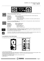
Displays the preset
combustion power
, and consequently the pellet consumption
,
by the number of
bars that are
lit up around the flame symbol, using this logic:
One bar lit:
Minimum combustion power (and therefore with minimum pellet consumption).
Two bars lit:
Second combustion power.
Three bars lit:
Third combustion power.
Four bars lit:
Fourth combustion power.
Five bars lit:
Maximum combustion power (and therefore with maximum pellet consumption).
No bars lit:
The appliance is OFF.
Displays the preset
ventilation power
, and consequently the room fan speed
,
by the number of
bars that are lit
up around the fan symbol, using this logic:
One bar lit
:
Minimum ventilation power.
Two bars lit:
Second ventilation power.
Three bars lit:
Third ventilation power.
Four bars lit:
Fourth ventilation power.
Five bars lit:
Fifth ventilation power.
Six bars lit
:
Maximum ventilation power.
Dashes appear along the top of the display, and each dash corresponds to one day of the week set by the user
(e.g. 1 corresponds to Monday, 2 corresponds to Tuesday… etc.).
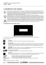
The operating status of the appliance appears below these dashes, that is START, OFF or WORK. And the current
time set by the user appears below this word.
The presence in the display of the clock symbol indicates that the CHRONO programming has been enabled; if this
symbol does not appear it means that the CHRONO programming has been disabled.
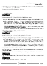
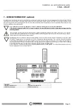
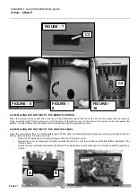
5.2 DESCRIPTION OF THE POWER PANEL
The components of the power panel, located on the rear side of the appliance, are described below:
1) Cap for reset thermostat button.
If the reset thermostat overheats stop the pellet feeder. The appliance must cool down before you can restart the appliance. After
verifying and eliminating the causes of the overtemperature, undo the protective cap and press the button.
2) Test indicator light for pellet feed motor.
The light comes on simultaneously with the activation of the pellet feed motor.
3) Outlet RJ 45 to connect Wi-Fi module.
4) Main switch 0/I.
M
DETTAGLIO M
1
2
3
4
5
6


