Page 13
Installation, use and maintenance guide
14:30
WORK
3
2
5
4
8
1
7
6
11
13
12
14
14:30
WORK
Zona del display dove viene visualizzato il giorno
corrente (per esempio 3 pallini = mercoledì).
Indicatore livello
di ventilazione
Zona del display
visualizzati fasi di funzionamento, ora....
dove vengono
"Themocomfort On "
ovvero connesso
Indicatore livello
di combustione
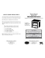
Hang the unit on the wall bracket A; once the appliance is suspended, push it firmly against the wall and tighten the screws B.
When carrying out this operation, take care to match up the support hooks (See details C and D in Figure 7).
Once you have completed this operation, remove the base by undoing the 4 screws that fix it to the structure of the appliance. It is
recommended to tighten the screws in the appliance once the base has been removed. Next assemble the front panel and the left
and right side panels.
ATTENTION: considering the weight of the appliance, it is recommended to use anchor bolts suitable for the type of
wall to which the appliance is mounted.
ATTENTION: it is necessary to ensure that the wall plaster and finish can resist a working temperature of 80 °C.
Given the working temperatures of the appliance it is normal for the wall to blacken, particularly if it is a light colour,
after a season of operation.
5 – DESCRIPTIONS OF CONTROLS
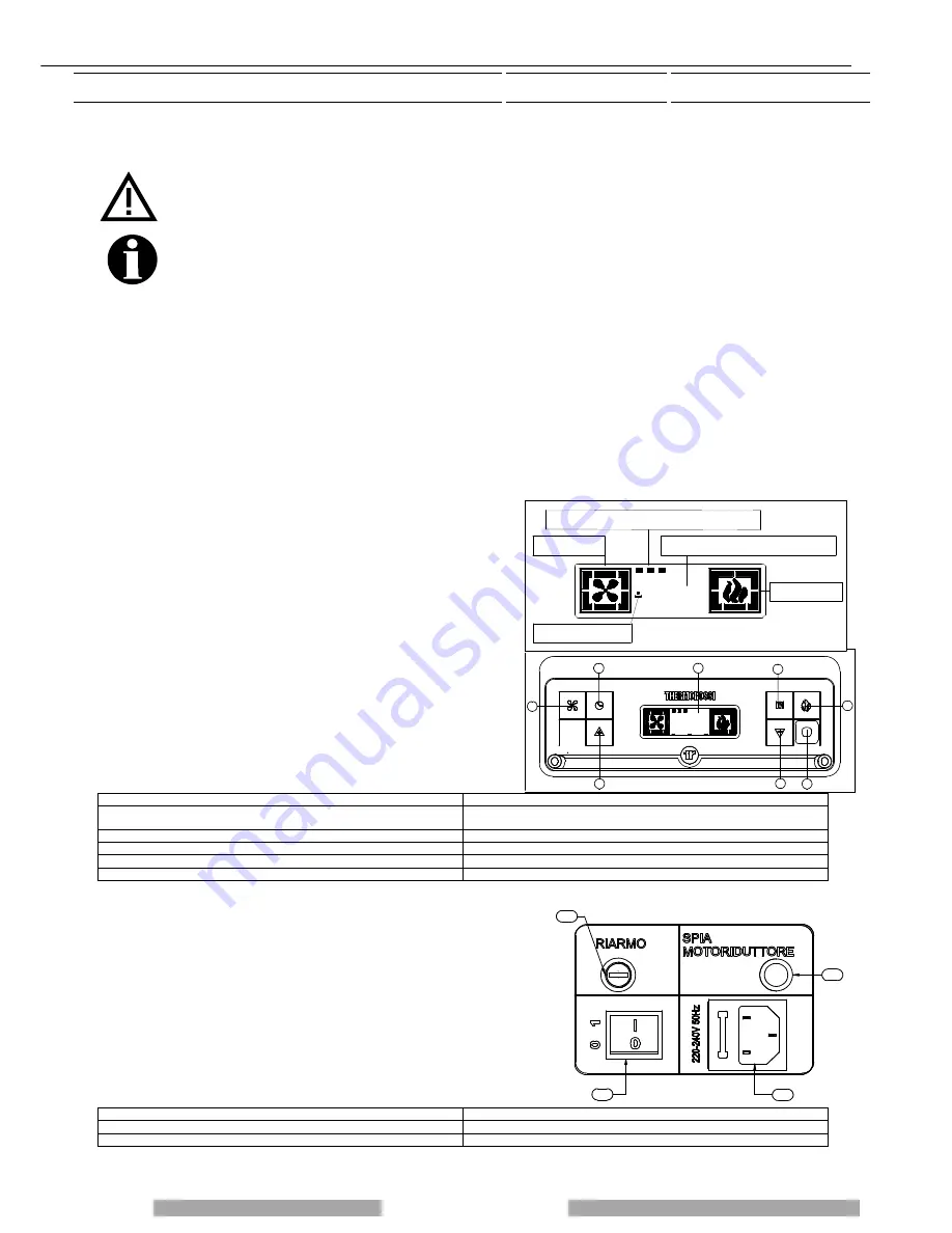
There are two main control pushbuttons marked with the ventilation symbol (2) and the symbol of the flame (1).The flame
pushbutton (1) sets the power of the appliance with 5 levels available which are activated as the 5 bars light up in sequence on the
display (7). The off cycle is activated when all power bars are turned off. The fan button (2) controls the ventilation of the appliance.
It is activated when the smoke, detected by the smoke probe, reaches a temperature over 60°C.
The fan can be set to any of 6 speed levels displayed by the 6 bars progressively coming on on the display (7): when the appliance
is on the ventilation cannot be switched off.
5.1 DESCRIPTION OF THE CONTROL PANEL AND BACK PANEL
5.1.1 DESCRIPTION OF THE CONTROL PANEL
All controls and indicators are presented here below:
(1) Appliance on/off and flame adjustment button When you press
this button the appliance switches to START/WORK/ OFF
(appearing on the display 7). Press repeatedly to activate up to 5
bars on the display (7)
(2) Ventilation setting button Press this button to set the desired
level of ventilation: you can select up to a maximum of 6 speeds,
acknowledged by the corresponding bars lighting on the display (7).
One bar is always lit up even in OFF status.
(3) (4) Auxiliary setting buttons
Keys (3) and (4) are operating buttons necessary when on-off cycles
are programmed, for operative levels, clock setting, etc..
(5) Programming Enable / Disable / Chrono Reset buttons
(6) “MENU” selection button To access the main menu press the
button marked with 6. Press button 6 repeatedly to scroll the various
windows: date, programming setting,...
(7) Display
(8) Infrared remote control sensor
LEGENDA
KEY
Zona del display dove viene visualizzato il giorno corrente (per esempio 3
pallini = mercoledì)
Display area in which the current day is displayed (for example, 3 dots =
Wednesday)
Indicatore livello di ventilazione
Ventilation level indicator
Zona del display dove vengono visualizzati fasi di funzionamento, ora…
Display area in which the operation steps are displayed, time...
Indicatore livello di combustione
Combustion level indicator
“Thermocomfort On” ovvero connesso
"Thermocomfort On" i.e. connected
5.1.2 RH SIDE PANEL OF THE HEATER
A description of the functions of the buttons and LEDs on the rear panel:
(11) Main switch 0-1
(12) Electrical power outlet 220-240V 50 Hz.
(13) Overtemperature reset thermostat button cap
In the event of overtemperature this safety thermostat stops the loading of
pellets. To restart the appliance you need to wait until it cools down, then
verify the cause for the overheating, remove the cause, unscrew the
protective cap and press the button (13).
(14) Feed motor test indicator light When the pellet screw feeder is set
in motion the light must come on.
LEGENDA
KEY
Riarmo
Reset
Spia motoriduttore
Ratio motor led
Содержание SlimQuadro 11
Страница 2: ...Page 2 Installation use and maintenance guide ...
Страница 5: ...Page 5 use and maintenance guide EC DECLARATION OF CONFORMITY ...
Страница 26: ...Page 25 and maintenance guide ...
Страница 42: ...Page 41 and maintenance guide NOTES ...
Страница 43: ...Page 42 lation use and maintenance guide NOTES ...


