pg. VIII
4
4
4
4
4
INST
INST
INST
INST
INSTALLA
ALLA
ALLA
ALLA
ALLATION
TION
TION
TION
TION
4 . 1
4 . 1
4 . 1
4 . 1
4 . 1
HEA
HEA
HEA
HEA
HEATER / BOILER L
TER / BOILER L
TER / BOILER L
TER / BOILER L
TER / BOILER LOCA
OCA
OCA
OCA
OCATION
TION
TION
TION
TION
CAUTION : Always use trolleys to move the appliance and the appliance
must always be in a vertical position. The casing for the H2O is packed
separately. On the contrary, to unpack the Compact, once the wood
crate has been removed, remove the casing (in reverse order as set out
in para.4.2.3). Remove the screws at the base of the heater / boiler and
remove the base from the bottom pallet.. Follow the general guidelines
set out in paragraph 1.1 to the letter. Above all ensure that the flooring of
the room where the heater / boiler will be installed is capable of bearing
the weight of the appliance plus the weight of the water contained in it
and the weight of the pellets in the hopper.
CAUTION: The room in which the appliance will operate must be adequately
ventilated (minimum air intake for an air flow of 1300 m3/h).
The heater / boiler must be positioned at a minimum safe distance
from walls and furnishings. This distance will have to be increased
considerably if the objects surrounding the appliance are inflammable
(matchboarding, furniture, curtains, picture frames, sofas, etc...). The
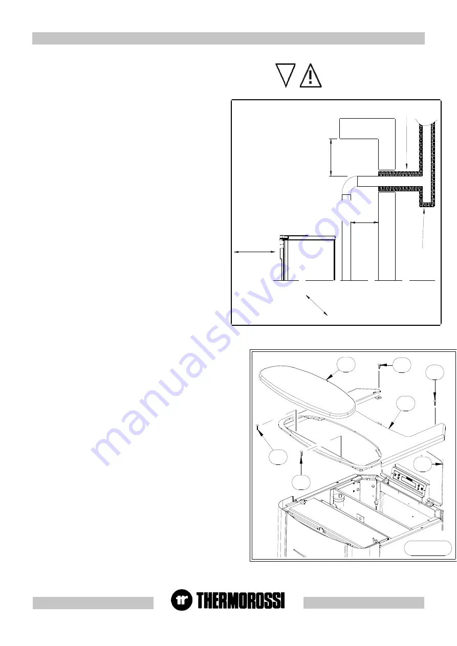
recommended minimum distances are illustrated in the drawing below
on the right. Installation in the vicinity of heat-sensitive materials is only
permitted if suitable insulating protection is provided for (ref. Uni
10683).
4 . 2 . 1
4 . 2 . 1
4 . 2 . 1
4 . 2 . 1
4 . 2 . 1
HO
HO
HO
HO
HOW
W
W
W
W T
T
T
T
TO MOUNT H2O 25 HEA
O MOUNT H2O 25 HEA
O MOUNT H2O 25 HEA
O MOUNT H2O 25 HEA
O MOUNT H2O 25 HEATER CASING
TER CASING
TER CASING
TER CASING
TER CASING
200 mm SE MATERIALE CO
MBUSTIBILE
200 mm SE MATERIALE
COMBUSTIBILE
45
0
m
m
S
E
M
AT
ER
IA
LE
C
OM
BU
ST
IB
IL
E
45
0
m
m
S
E
M
AT
ER
IA
LE
C
OM
BU
ST
IB
IL
E
Tee ispezionabile
ISO
LANTE TERMICO
After positioning and levelling the heater by raising or lowering the mounting
feet, connecting it to the heating system and to the electrical system, the next
step is to mount the casing as shown in the image:
Carry out the steps described below as illustrated in figures 1,2,3:
- Open the pellets feed cover and remove the screws (C) (Figure 1).
- Remove the complete cover (B) (Figure 1).
- Next undo the first 2 screws (L) then remove the side panels (I) (Figure 2).
- Next fix the ceramic tiles on the side (G) as shown in Figure 3.
Take care not to over-tighten the nuts (F) as this could cause the tile to break;
this type of damage is not covered by warranty.
- After fixing the 4 ceramics proceed to mount the side panel (I) (Figure 2).
-Reassemble the complete cover (B) by fixing it with the screws (C) then
place the ceramics (A).
4 . 2
4 . 2
4 . 2
4 . 2
4 . 2
MOUNTING HEA
MOUNTING HEA
MOUNTING HEA
MOUNTING HEA
MOUNTING HEATER
T E R
T E R
T E R
T E R
/ BOILER
/ BOILER
/ BOILER
/ BOILER
/ BOILER
CASING
CASING
CASING
CASING
CASING .....
C
C
Figura 1
B
A
D
C
C
K E Y
200 / 450 mm if
combustible material
Heat insulating material
Inspectable Tee element
Figure
LEGENDA
200 / 450 mm se
materiale
combustibile
Isolante termico
Tee ispezionabile
Figura


