Thermopatch Deco-Print DP2000T Скачать руководство пользователя страница 20

thermopatch.com

20

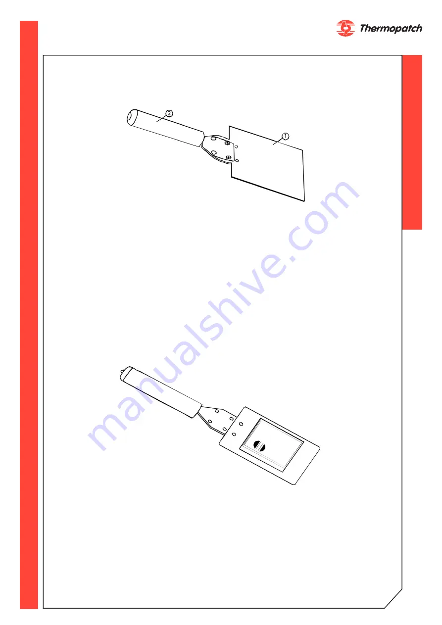
INSERTING THE PRINTING PLATE

The above drawing shows a DP2000T Printing Plate (Item 1) (CUSTOM PART) and a Printing 

Plate Holder (Item2) P/N (46007). The Printing Plate Holder is provided for installation and 

removal of the Printing Plate. 
• 

With the artwork facing down on the Printing Plate, apply a downward force just 

enough to slide the Printing Plate Holder forward. This locks the Printing Plate into place. 
• 

Insert the plate into the plate mounting brackets on either side of the iron. 

• 

Slide the plate in fully. 

• 

Apply the same downward force and slide the Printing Plate Holder away from the 

machine. 
To remove the Printing Plate from the machine, just reverse the process. The Printing Plate 

is extremely HOT so caution must be taken when removing and placing it on a heat protec-

tive surface. Avoid any side to side motion of the Plate Holder while inserting or withdrawing 

Print Plates. This motion tends to bend side guides and loosen heater mounting screws.

Note:

 If you bump the touch guard, press the CLEAR button on the controller box to reset.

Choosing The Platen

Be sure to use the proper platen. Use the hard rubber platens for printing, and the soft rub-

ber platen for heat sealing and dry ink transfers. There should be a distance of at least 1/8” 

to 1/4” between the printed image and the outer edge of the platen.

Содержание Deco-Print DP2000T

Страница 1: ...G V1 0 original version June 2022 based on TP Corp REV1215 ATTENTION All persons involved in installation commissioning operation maintenance and re pair of this product should be made available to th...

Страница 2: ...The products by Thermopatch are designed with special attention to your convenience Should you discover any fault or damage upon receipt of this product please contact your local Thermopatch vendor T...

Страница 3: ...parts indentification and location 27 Drawing 01 DP 2000 T Machine Assembly 27 Drawing 02 Platen Assembly 28 Drawing 03 Press Arm Assembly 29 Drawing 04 Heater Assembly 30 Drawing 05 Support and Swit...

Страница 4: ...ubber platen C tape and a printing plate not included The printing plate is ordered separately in one of three configurations 1 With the customer s logo 2 With a plate with tracks or 3 With a combinat...

Страница 5: ...f a printing plate briefly striking the inked ribbon against the material to be marked The machine is an air operated machine that uses a foot pedal in cluded to initiate the printing cycle WARNING An...

Страница 6: ...m Ink Ribbon Width 4 3 2 and 1 inch 102 76 51 and 25 mm Multiple colors and widths any combinations up to 4 total width Opening Height Between Printing Plate and Platen 5 0 127 mm Clearance From Back...

Страница 7: ...AUGE MUST NOT EXCEED 100 PSI 7 0 BAR CAUTION THE PRINTING HEAD AND PLATE MAY REACH TEMPERATURES AS HIGH AS 550 F 288 C DURING NORMAL OPERATION ALWAYS KEEP HANDS CLEAR OF THE PRINTING HEAD WHEN OPERATI...

Страница 8: ...en cleaning the machine ATTENTION In case of emergency press the emergency stop button ATTENTION Take care that there is enough space around the machine Cables and connections must not get pinched Alt...

Страница 9: ...use the original packaging The machine has to be lifted by the screw that is fixing the swiveling arm and the handle on the front of the machine 5 2 Storage When the machine needs to be stored Thermop...

Страница 10: ...tions 6 1 Setting up the DP 2000 T Step 1 Refer to Figure 1 Loosen the two screws on the top of the case in the back and install the control box bracket Item 4 Plug one side of the display cable Item...

Страница 11: ...opatch com 11 Plug the other end of the display cable Item C into the connector on the side of the ma chine Step 2 Turn the Emergency Stop switch Item A in the direction of the arrow to make sure it i...

Страница 12: ...e male hose adaptor Item C Step 4 Refer to Figure 6 This is the Electrical Enclosure Assembly found on the right side of your machine Connect the foot pedal plug into the FOOTSWITCH Plug Item A Connec...

Страница 13: ...thermopatch com 13 Step 5 Refer to below Place flange assemblies Item A on supply and take up shafts Item B...

Страница 14: ...thermopatch com 14...

Страница 15: ...thermopatch com 15...

Страница 16: ...G button to feed the transfer image until the image is in the center of the sealing platen 4 Press the MENU button 5 Press the ENTER button until the display reads SET FEED LENGTH 6 Subtract 2 tenths...

Страница 17: ...move the transfer sensor onto the space between the transfer images and tighten the clamp screw 10 Press the TRANSLUCENT button and hold it until the lights on the sensor stop blinking NOTE If green...

Страница 18: ...ed Adjustment The first step is to adjust the feed This feed value advances the tape after printing to the amount of the entered value to set up for the next print Using the control box the user adjus...

Страница 19: ...l screws are turned clockwise and the platen is put in its lowest position Setup for 2 or More Ribbons 1 Multiple ribbons of different colors are threaded the same as a single ribbon shown in Figure 1...

Страница 20: ...the Printing Plate Holder away from the machine To remove the Printing Plate from the machine just reverse the process The Printing Plate is extremely HOT so caution must be taken when removing and pl...

Страница 21: ...ightly to reduce waste Correcting Take Up Problems Check that the used ribbon or transfer tape on the take up shaft is not trying to fold over on the flange If it is the take up flanges can be moved t...

Страница 22: ...the Daily Counter DC is displayed The Mode button switches the display to menu mode with 2 selections MACHINE SETUP JOB SETUP The MACHINE SETUP menu is used to set 1 Display language English Nederland...

Страница 23: ...00 degrees F or to suit with UP or DOWN button Press ENTER and set Feed Length at 4 inches by pressing UP or DOWN button Press ENTER and set Print Time at 2 seconds by pressing UP or DOWN button Press...

Страница 24: ...eplace Check Repair No heat Machine is unplugged or out let has no power Electrical power switch is not ON or is defective Temperature reading is in correct Print Head heat is defective Heat sensor is...

Страница 25: ...ow Temperature is too low Time setting is too low See pg 19 See pg 23 See pg 23 Parts of design are not print ed In ribbon feed not working properly Rubber print platen is dirty or worn In ribbon to p...

Страница 26: ...g messages will appear Line 1 Meaning Response Heater Failure Logic board Temperature control board is either bad or unplugged Heater Failure Heat Sensor Temperature sensor is either bad or discon nec...

Страница 27: ...05 F PHS 8 32 X 3 8 LG 4 9 21021 07 C NO 10 Spring 11 10 21061 02 E BUTTON HD 10 32 X 3 8 LG 11 11 20220 37 SHIELDED SERIAL CABLE 1 12 21028 38 RUBBER BUMPER 4 13 21060 04 H BHS 10 32 X 5 16 LG 4 14 4...

Страница 28: ...X 3 4 HD 4 7 21062 03 D FLAT SOC HD SCR 8 32 X 1 2 4 8 24075 26 SPRING COMPRESSION 4 9 46833 COVER PLATEN BASE 1 10 45637 HARD RUBBER PLATEN 2 11 21069 03 E PHS 6 32 X 1 4 LG SS 4 12 45620 STOP PLATE...

Страница 29: ...R SPLIT 1 4 10 11 21011 04 H SET SCR 8 X 32 X 3 16 2 12 21022 12 THRUST WASHER 3 8 I D X3 4O D X 06TK 2 13 45573 SHAFT CENTER LINK PIVOT 1 14 21011 05 L SET SCW CUP 1 4 20 X 1 4 LG 4 15 45583 SHAFT LO...

Страница 30: ...IT 2 6 21050 192 SHCS 5 16 18 X 2 0 LG S S 2 7 21021 06 C NO 8 SPLIT LOCKWASHER 10 8 21069 05 E PHS 6 32 X 3 8 LG SS 2 9 21069 03 E PHS 6 32 X 1 4 LG SS 6 10 21021 06 B LOCKWASHER EXT NO 8 1 11 21069...

Страница 31: ...12 NUT PLATE SEAL SWITCH 1 7 20055 73 SWITCH MICRO 1 8 21033 03 C SPRING PIN 1 8 X 3 8 LG 1 9 21029 48 BUT HD 8 X 32 X 3 8 2 10 21021 06 C NO 8 SPLIT LOCKWASHER 2 11 21023 22 WASHER FLAT NO 6 2 12 210...

Страница 32: ...R PLATE ASSY SEE PAGE 39 1 6 21011 04 K SET SCREW 10 32 X 3 16 LG 4 7 COVER ASSY HEAD SEE PAGE 5 13 1 8 21063 05 K SHCS 1 4 20 X 5 8 LG 4 9 21021 09 C LOCKWASHER SPLIT 1 4 4 10 FRONT PLATE ASSEM SEE P...

Страница 33: ...2 13 46941 THUMB SCREW ASSY 1 4 20 X 5 LG 1 14 46943 SPACER MACHINE HEAD PLATES 1 15 46921 SPACER HEAD PLATE 2 16 21021 07 C NO 10 SPLIT LOCKWASHER 16 17 21021 09 C LOCKWASHER SPLIT 1 4 1 18 46903 BRA...

Страница 34: ...4 2 8 D 9701 E RING 3 16 2 9 D 9702 E RING 1 4 2 10 24080 36 SPRING EXT LE 031C 1 2 11 21063 03 J SHCS 10 32 X 3 8 LONG 6 12 LASER ASSY SEE PAGE 40 1 1 DANCER ROLL ASSY SEE PAGE 41 1 13 46881 SHAFT T...

Страница 35: ...1 2 46934 PIVOT BLOCK LASER 1 3 46933 PIN LASER BLOCK 1 4 46935 BRACKET LASER BLOCK 1 5 D 9701 E RING 3 16 2 6 21058 03 F PHS 8 32 X 1 4 LG 2 7 21021 06 C NO 8 SPLIT LOCKWASHER 2 8 21011 04 H SET SCR...

Страница 36: ...K LEAF SPRING 1 2 46914 LEAF SPRING 1 3 46913 HANDLE SPRING 1 4 46909 SHAFT PIVOT 1 5 46905 DANCER ROLL ARM 1 6 46910 ARM ASSY SPRING 1 7 21011 04 K SET SCREW 10 32 X 3 16 LG 2 8 D 9702 E RING 1 4 2 9...

Страница 37: ...10 45606 TOUCH GUARD WELDMENT 1 11 45605 SPACER TOUCH GUARD 2 12 45604 INSULATOR TOUCH GUARD 2 13 21063 08 K SHCS 1 4 20 X 1 0 LG 2 14 21021 09 C 1 4 SPLIT LOCKWASHER 2 15 45657 PLATE R H SWITCH MTG...

Страница 38: ...ION QTY 1 46884 COVER HEATER 1 2 45597 TAPE GUIDE 2 3 46938 LABEL DP2000T FRONT 1 4 20055 75 STOP SWITCH ACTUATOR 1 5 20056 28 CONTACT BLOCK E STOP 1 6 21021 06 C NO 8 SPLIT LOCKWASHER 4 7 21069 03 F...

Страница 39: ...45 CONN 1 4 MPT X 3 8 TUBE 5 8 22030 09 POLY FLOW 3 8 O D X 1 4 I D 65 5 9 22045 89 VALVE IN LINE CHECK 1 4 NPT 1 10 22010 56 AIR CYLINDER 2 1 2 BORE 3 1 2 STROKE 1 11 22030 53 BRANCH WYE 1 4 MPT X 3...

Страница 40: ...1 6 22045 89 VALVE IN LINE CHECK 1 4 NPT 1 7 22046 09 AIR FLOW CONTROL RT ANGLE 1 4 NPT 2 8 22015 34 ELBOW 1 4 MPT X 3 8 TUBE 1 9 22005 45 CONN 1 4 MPT X 3 8 TUBE 5 10 21058 15 I PAN HEAD SCREW 1 4 2...

Страница 41: ...thermopatch com 41 Drawing 15 Electronics Module Drawing 16 Main Electronics Module...

Страница 42: ...thermopatch com 42 Drawing 17 AC Harness...

Страница 43: ...thermopatch com 43 Drawing 18 DC Harness...

Страница 44: ...19 Head Cover Assembly ITEM NO PART NUMBER DESCRIPTION QTY 1 46883 COVER HEAD 1 2 21029 60 THUMB SCREW 1 DIA KN D HD 1 4x20x1 1 4 LG 2 3 D 7212 ACORN HEX NUT 1 4 20 2 4 45426 LABEL HIGH VOLTAGE 1 5 4...

Страница 45: ...aintain a filtered air supply Check air filter daily Drain by pushing up on button at bottom of filter bowl General Keep inside of machine free of foreign material including lint Teflon Fiberglass Shi...

Страница 46: ...EMC 2016 Electrical Equipment Safety Regulations LVD 2016 Supply of Machinery Safety Regulations 2008 The Netherlands Almere 01 06 2022 Jan Bausch Director 10 Declarations of conformity We Thermopatch...

Страница 47: ...re in good faith and whilst every care has been taken in preparing these documents Thermopatch B V makes no representations and gives no warranties of whatever nature in respect to these documents inc...

Страница 48: ...h com Thermopatch European Headquarters The Netherlands T 31 36 549 11 11 F 31 36 532 03 98 sales thermopatch nl Thermopatch Australia Pty Ltd Australia T 61 395325722 F 386 2 80 55 232 marktpatchaust...

Отзывы: