Engine Maintenance (Rev. 04/02)
48
13. Test the relay.
a.
Use a jumper to connect the 85 terminal on the
relay to the positive battery terminal.
b.
Use another jumper to connect the 86 terminal on
the relay to a CH circuit.
c.
If the relay does not energize, it is defective.
Replace the relay.
d.
If the relay does energize, the timer is defective.
Replace the fuel solenoid timer PC board.
14. Turn the unit OFF after completing the test procedure.
Fuel Solenoid Replacement
1.
Disconnect the fuel solenoid wire connector from the
main wire harness and remove the old fuel solenoid.
2.
Connect the new fuel solenoid wire connector to the
main wire harness.
3.
Use the microprocessor keypad to enter the Relay
Board Test Mode. Refer to the appropriate Micropro-
cessor Operation and Diagnosis Manual for detailed
information about the Relay Board Test Mode.
4.
Energize the fuel solenoid by energizing the run relay
[RUNR] with the Relay Board Test Mode.
NOTE: The fuel solenoid must be energized when it is
being installed. If it is not, the plunger and the linkage
may not line up correctly and the fuel solenoid will
not function properly.
5.
Place the O-ring in the groove in the end of the fuel
injection pump. Make sure that the O-ring is positioned
correctly during installation to avoid damage and leaks.
6.
Install the new fuel solenoid.
7.
Place the On-Off switch in the OFF position after
installing the fuel solenoid.
ENGINE VALVE CLEARANCE
ADJUSTMENT
1.
Remove the rocker arm cover.
2.
Remove the round cover (plug) from the timing mark
access hole on the front of the bell housing.
3.
4.
Place the engine at top dead center of the compression
stroke for the number one cylinder.
a.
Rotate the engine in the normal direction of rota-
tion (clockwise viewed from the water pump end)
until the 1-4 timing mark on the flywheel lines up
with the index mark in the timing mark access
hole.
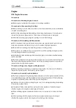
1.
Fuel Solenoid
2.
O-ring
3.
Groove in Fuel Injection Pump
Fuel Solenoid Components
aea635
CAUTION: Loosen all of the injection lines at
the injection nozzles to prevent the possibility
of the engine firing while it is being rotated.
Содержание SB-III 30 SR+
Страница 4: ......
Страница 8: ......
Страница 10: ...ii ...
Страница 14: ...4 ...
Страница 24: ...Unit Description Rev 04 02 14 Unit Photos Front View AGA231 ...
Страница 25: ...Unit Description Rev 04 02 15 1 Defrost Damper 2 X430 Compressor 3 TK 486 Engine Back View AEA698 2 3 1 ...
Страница 28: ...18 ...
Страница 66: ...56 ...
Страница 98: ...88 ...
Страница 110: ...100 ...
Страница 111: ...101 Early Model Coiled Wire Fuse Link Wiring Schematic ...
Страница 112: ...102 Early Model Coiled Wire Fuse Link Wiring Diagram Page 1 of 4 ...
Страница 113: ...103 Early Model Coiled Wire Fuse Link Wiring Diagram Page 2 of 4 ...
Страница 114: ...104 Early Model Coiled Wire Fuse Link Wiring Diagram Page 3 of 4 ...
Страница 115: ...105 Early Model Coiled Wire Fuse Link Wiring Diagram Page 4 of 4 ...
Страница 116: ...106 Late Model Fuse Link in Battery Cable Wiring Schematic ...
Страница 117: ...107 Late Model Fuse Link in Battery Cable Wiring Diagram Page 1 of 4 ...
Страница 118: ...108 Late Model Fuse Link in Battery Cable Wiring Diagram Page 2 of 4 ...
Страница 119: ...109 Late Model Fuse Link in Battery Cable Wiring Diagram Page 3 of 4 ...
Страница 120: ...110 Late Model Fuse Link in Battery Cable Wiring Diagram Page 4 of 4 ...