ECO ULTRA Electric Boiler
Installation, Use and Care Manual
(Revision June 2017)
, Page
12.
3.6 SYSTEM SETUP
Figures 2 to 8 indentify and show location of the
different components. They also provide typical
heating system installation. External components
location may vary in order to accommodate
specific installation and local codes and
regulation.
3.6.1 Connecting the boiler
The boiler heating supply and return connections
are located on the left or right side and are
1”
NPTM for Model 50 and 1-
¼’’ NPTM for model
70. The connections at the left or right can be
used. The important thing is that the fluid
circulation must be made from the bottom to the
top (see figure 1)
Unions are recommended on the inlet and outlet
pipes to disconnect the water heater easily for
servicing if necessary.
Dielectric (insulating) unions should be used if
copper-steel connections are made.
Insulate all pipes containing hot water, especially
in unheated areas.
3.6.2 Flow-check valve
If the heating system uses a single or multiple
circulators without motorized zone valves,
a flow-
check valve must be installed
to avoid all
possibility of gravity flow and heat loss during
non-draw periods. Modern circulators are
typically provided with spring loaded check valves
that will provide adequate protection.
If the heating system uses motorized zone
valves, these will provide adequate protection.
3.6.3 Pressure relief valve
The boiler is delivered with a factory installed tank
pressure relief valve set at 207 kPa (30 psi).
NEVER
replace the pressure relief valve by a
higher set pressure one.
Connect the outlet of the relief valve downward
toward a safe location.
Relief valve outlet pipe diameter must not be of
smaller diameter than the relief valve outlet. The
oulet pipe end must be visible in order to observe
any relief incident and be protected from freezing.
NEVER cap or plug a pressure relief valve
outlet. The pressure relief valve is a safety
apparatus and preventing its proper operation
may cause death, injury or property damage.
3.6.4 Expansion tank
When operating the ECO ULTRA and the heating
system, pressure will vary between 83 kPa and
193 kPa (12 psi to 28 psi). The operating
pressure is affected by the type of heating system
and the size of the expansion tank installed.
The expansion tank is used to absorb the
increase of water volume from the boiler and the
system when it is working.
The model selection should be based on the
maximum working temperature and the water
volume of the total system. For example, a
system with radiators contains much more water
volume than a baseboards system. Likewise, the
ECO ULTRA also contains an important volume
of water that has to be added :
ECO ULTRA 50 : 48 usgal
ECO ULTRA 70 : 71 usgal
With this information, the installator or distributor
should be able to make an appropriate selection
for an expansion tank.
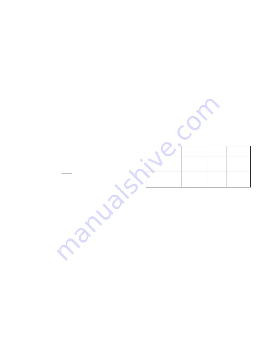
Here are some minimal recommendations for
different types of heating systems.
ECO ULTRA
Baseboards
Radiant
floor
Cast-iron
radiators
ECO ULTRA 50
#30
#30
#60
ECO ULTRA 70
#60
#60
#90
The expansion tank is generally installed on the
wall or ceiling. It also has to be well supported.
3.6.5 Water pressure regulator
The boiler should be installed in such a way that
it can automatically be fed with water in the event
of a pressure drop.
The minimum pressure obtained when the
system is cold is generally 12 psi (83 kPa).
This accessory shall be equipped with one or
more check valves to avoid all possibilities of the
boiler water returning to the potable water supply
network (local regulation should be applied)
3.6.6 Automatic Air Vent
The ECO ULTRA has a factory installed tank
automatic air vent. This air vent function is to vent
any air present in the tank.
For proper operation, do not cap or block the air
bleeder outlet.
For proper operation of the heating system, it may
be necessary to add air bleeders to the heating
system circuits.


