Bigwater 780e
CL-W0169
English
English
19
20
a
f
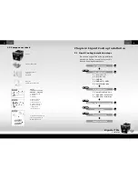
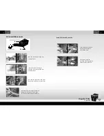
Step 1: Connect the 4-pin power connector of BigWater 780e to power supply.
Power connector cable (a)
2.8 ESA PCB Installation
Please following installation procedure.
Please note that the pins of VCC &
GND must be connected correctly or
it may cause some damage.
Signal
Pin
D-
D+
1(Red wire)
2
3
4
Ground
VCC(+5V)
D-
D+
Ground
VCC(+5V)
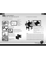
Step 2: Connect to USB connector on the motherboard.
USB connector cable(f)
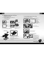
Step 3:
Connect LED cable from the ESA chassis if
you are using this Watercooling with Tt ESA chassis as well.
Case LED cable(b)
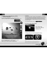
There are two LED connectors on the ESA chassis PCB for Tt ESA
watercooling and Tt ESA power supply. Please connect the ESA Watercooling
status LED cable to the correct connector for ESA Bigwater 780e. For
more detail information, please refer to your Thermaltake ESA
chassis user manual.
Figure 1
ESA Chassis PCB
ESA Watercooling PCB
b


