background image

SECTION 5: SERVICE

26

Manual 0-2748

3.  Disconnect gas supply hose from barbed fitting.

4.  Turn the Cover counterclockwise and remove it

from the Filter Housing.  The Filter Element is lo-
cated inside the Housing.

5.  Remove the Filter Element from the Housing and

set Element aside to dry.

6.  Wipe inside of housing clean, then insert the re-

placement Filter Element cup side first, as shown
below.

7.  Replace Housing on Cover.

8.  Reattach gas supply hose to barbed fitting.

NOTE

If unit leaks between housing and cover, inspect
the "O" Ring for cuts or other damage.

5.03  Common Operating Problems

WARNINGS

Disconnect primary power at the source before dis-
assembling the power supply, torch, or torch leads.

Frequently review the Important Safety Precau-
tions (page 1). Be sure the operator is equipped with
proper gloves, clothing, eye and ear protection.
Make sure no part of the operator’s body comes into
contact with the workpiece while the torch is acti-
vated.

CAUTION

Sparks from the cutting process can cause damage
to coated,  painted, and other surfaces such as glass,
plastic and metal.

NOTE

Handle torch leads with care and protect them from
damage.

A.  Piloting

Piloting is harder on parts life than actual cutting because
the pilot arc is directed from the electrode to the tip rather
than to a workpiece. Whenever possible, avoid excessive
pilot arc time to improve parts life.

B.  Torch Standoff

Improper standoff (the distance between the torch tip and
workpiece) can adversely affect tip life as well as shield
cup life. Standoff may also significantly affect the bevel
angle. Reducing standoff will generally result in a more
square cut.

C.  Edge Starting

For edge starts, hold the torch perpendicular to the work-
piece with the front of the tip at the edge of the work-
piece at the point where the cut is to start. When starting
at the edge of the plate, do not pause at the edge and
force the arc to "reach" for the edge of the metal. Estab-
lish the cutting arc as quickly as possible.

D.  Direction of Cut

In the torches, the plasma gas stream swirls as it leaves
the torch to maintain a smooth column of gas. This swirl
effect results in one side of a cut being more square than
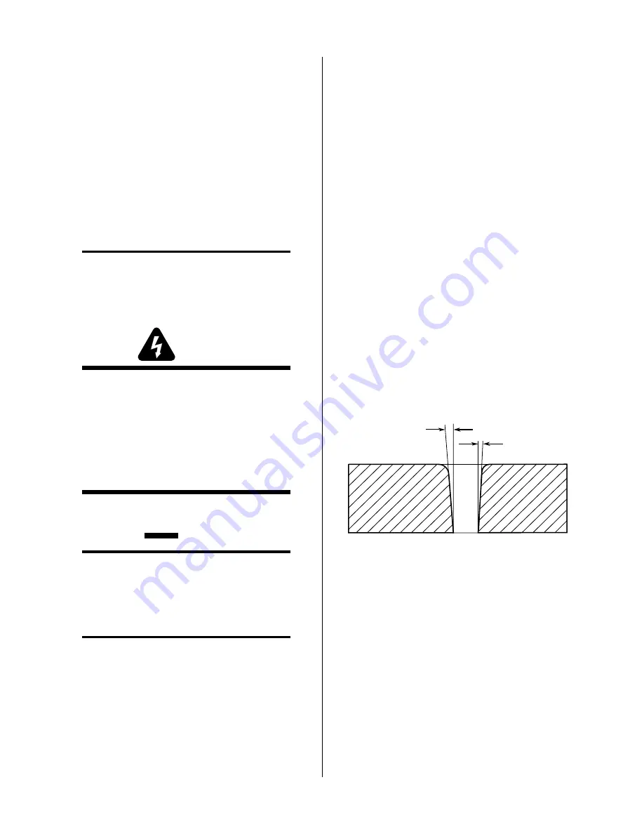
the other. Viewed along the direction of travel, the right
side of the cut is more square than the left (Refer to Fig-
ure 5-2). To make a square-edged cut along an inside di-
ameter of a circle, the torch should move counterclock-
wise around the circle. To keep the square edge along an
outside diameter cut, the torch should travel in a clock-
wise direction.

Right Side

Cut Angle

Left Side

Cut Angle

A-00512

Figure 5-2  Side Characteristics Of Cut

E.  Dross

Generally when dross is present on carbon steel, it is re-
ferred to as either "high speed or slow speed dross".

"High speed dross" usually forms a narrow bead along
the bottom of the cut edge and is very difficult to remove.
"Slow speed dross" will be in larger quantities but does
not adhere tightly to the cut edge and can be easily re-
moved.

When cutting a troublesome steel, it is suggested that the
torch travel speed be reduced to produce "slow speed
dross".  Any required cleanup can then be done by scrap-
ping, not grinding.

Содержание PakMaster 100 XL plus

Страница 1: ...Manual No 0 2748 August 23 1999 Operating Manual A 02464 Air Plasma Cutting Power Supply ...

Страница 2: ... Thermal Dynamics Corporation Industrial Park No 2 West Lebanon New Hampshire USA 03784 603 298 5711 Copyright 1999 by Thermal Dynamics Corporation All rights reserved Reproduction of this work in whole or in part without written permission of the publisher is prohibited The publisher does not assume and hereby disclaims any liability to any party for any loss or damage caused by any error or omis...

Страница 3: ...Purchase Date Power Supply Torch Record Serial Numbers For Warranty Purposes ...

Страница 4: ......

Страница 5: ...ES 11 3 01 Introduction 11 3 02 Site Selection 11 3 03 Unpacking 11 3 04 Lifting Options 11 3 05 Input Power Connections 12 3 06 Input Voltage Selection 12 3 07 Primary Input Power Cable Connections 13 3 08 Gas Connections 14 3 09 Connecting Torch Leads 16 3 10 Work Cable And Ground Connections 17 3 11 Tip Saver Drag Cut Sensing Circuit 18 SECTION 4 OPERATION 19 4 01 Introduction 19 4 02 Functiona...

Страница 6: ...oduction 31 6 02 Ordering Information 31 6 03 Complete Power Supply Replacement 32 6 04 Replacement Parts 32 6 05 Options and Accessories 32 APPENDIX I INPUT WIRING REQUIREMENTS 33 APPENDIX II SEQUENCE OF OPERATION BLOCK DIAGRAM 34 APPENDIX III SYSTEM SCHEMATIC 36 ...

Страница 7: ...eep your head out of the welding fume plume Use an air supplied respirator if ventilation is not adequate to remove all fumes and gases The kinds of fumes and gases from the plasma arc depend on the kind of metal being used coatings on the metal and the different processes You must be very careful when cutting or welding any met als which may contain one or more of the follow ing Antimony Chromium...

Страница 8: ...eyes always wear a welding hel met or shield Also always wear safety glasses with side shields goggles or other protective eye wear Wear welding gloves and suitable clothing to pro tect your skin from the arc rays and sparks Keep helmet and safety glasses in good condition Replace lenses when cracked chipped or dirty Protect others in the work area from the arc rays Use protective booths screens o...

Страница 9: ...oute opération procédure ou renseignement général sur lequel il importe d insister davantage ou qui contribue à l efficacité de fonctionnement du système ATTENTION Toute procédure pouvant résulter l endommagement du matériel en cas de non respect de la procédure en question AVERTISSEMENT Toute procédure pouvant provoquer des blessures de l opérateur ou des autres personnes se trouvant dans la zone...

Страница 10: ...le 9 Débranchez l alimentation électrique avant tout tra vail d entretien ou de réparation Lisez et respectez toutes les consignes du Manuel de consignes INCENDIE ET EXPLOSION Les incendies et les explosions peuvent résulter des scories chaudes des étincelles ou de l arc de plasma Le procédé à l arc de plasma produit du métal des étincelles des scories chaudes pouvant mettre le feu aux matières co...

Страница 11: ...Office Washington D C 20402 4 Norme ANSI Z87 1 PRATIQUES SURES POUR LA PROTECTION DES YEUX ET DU VISAGE AU TRAVAIL ET DANS LES ECOLES disponible de l InstitutAméricain des Normes Nationales Ameri can National Standards Institute 1430 Broadway New York NY 10018 5 Norme ANSI Z41 1 NORMES POUR LES CHAUSSURES PROTECTRICES disponible auprès de l American National Standards Institute 1430 Broadway New Y...

Страница 12: ...APRÉPARATION À LA COUPE ET AU SOUDAGE DE CONTENEURS ET TUYAUX AYANT RENFERMÉ DES PRODUITS DANGEREUX disponible auprès de la American Welding Society 550 N W LeJeune Rd Miami FL 33126 15 Norme ANSI Z88 2 PRATIQUES DE PROTEC TION RESPIRATOIRE disponible auprès de l American National Standards Institute 1430 Broadway New York NY 10018 ...

Страница 13: ...tandardsAssociation standard C22 2 number 60 forArc welding equipment UL Underwriters Laboratory rating 94VO flammability testing for all printed circuit boards used ISO IEC 60974 1 BS 638 PT10 EN 60 974 1 EN50192 EN50078 applicable to plasma cutting equipment and associ ated accessories Extensive product design verification is conducted at the manufacturing facility as part of the routine design ...

Страница 14: ...products shall be as follows with the exception of XL Plus Series CutMaster 80XL Cougar and DRAG GUN A maximum of three 3 years from date of sale to an authorized distributor and a maximum of two 2 years from date of sale by such distributor to the Purchaser and with the further limitations on such two 2 year period see chart below The limited warranty period for XL Plus Series and CutMaster 80XL ...

Страница 15: ...mum 1 inch 25 4 mm cut capacity Hand torches are available in a 70 and 90 configuration a machine torch is available in a 180 configuration Torch leads are available in 25 ft 7 6 m or 50 ft 15 2 m lengths with fittings for simple in stallation Spare Parts Kits are available for the torches which provide an assortment of replacement torch parts NOTES For Torch information refer to the PCH M 80 manu...

Страница 16: ...is optional two stage air line filter is for use on compressed air shop systems Filters moisture and particulate matter from air stream to 5 0 microns This filter assembly is pre assembled at the factory and need only be attached to the power supply C High Pressure Regulators High pressure regulators are available for air and ni trogen The regulators are used to set the proper pres sure for the ty...

Страница 17: ...east 2 feet 0 6 m in the rear and at least 6 inches 0 15 m on each side for clearance Pro vide sufficient clearance in front of the unit to allow ac cess to the front panel controls minimum 6 inches or 0 15 m CAUTION Operation without proper air flow will inhibit proper cooling and reduce duty cycle 3 03 Unpacking Each component of the system is packaged and protected with a carton and packing mat...

Страница 18: ...oved to gain access to the input power connections and the input voltage selection WARNING Disconnect primary power at the source before as sembling or disassembling the Power Supply torch parts or torch and leads assemblies 1 Using a phillips head screw driver remove the five screws which secure the left side panel viewed from front of unit to the frame assembly Left Side Panel Screws 5 places A ...

Страница 19: ...election plug to the desired input connector for 220V 208 230 240V 380 415V or 460V input power operation 3 07 Primary Input Power Cable Connections Units ordered as 230V single phase will have a six foot power input cable and plug factory installed For all other units a cable must be provided by the end user Recom mended cable sizes are specified in Appendix I A Primary Power Cable Connection Pro...

Страница 20: ...tactor A 00914 L3 L2 Figure 3 6 Single Phase Jumper Wire Installation c Locate the ground stud and remove the top nut and washer d Install a lug terminal on the ground wire e Place the ground wire onto the ground stud and secure with the nut and washer f Insert the other two wires into the L1 and L2 terminals on the contactor g Tighten all set screws even the ones not used AC Input Power Cable L1 ...

Страница 21: ...alled refer to subsection D 3 Install the barbed fitting as shown below 4 Tighten the barbed fitting 5 Place an adjustable hose clamp customer supplied 1 4 6 5mm to 5 8 15 9mm over the gas supply hose Regulator Filter Assembly 1 4 NPT to 4 6mm Hose Fitting 4 6mm Gas Supply Hose Hose Clamp A 00916 Figure 3 7 Gas Connection to Regulator Filter Assembly D Optional Air Line Filter Installation Filteri...

Страница 22: ...clamp NOTE Supply hose must be at least 4 hose 1 4 in or 6 mm I D 3 09 Connecting Torch Leads WARNING Disconnect primary power at the source before as sembling or disassembling the power supply torch parts or torch and leads assemblies The Torch Leads must be properly installed to the Power Supply for proper operation Make all torch connections to the Torch Bulkhead Panel per the following NOTE Eq...

Страница 23: ...when install ing mechanized systems B Creating an Earth Ground 1 Install a ground wire not included between the sys tem and a solid earth ground also called star ground To create a solid earth ground drive a 1 2 in 12 mm diameter copper rod at least 6 8 ft 1 8 2 4 m into the earth so that the rod contacts moist soil over most of its length The required depth will vary depend ing on location see NO...

Страница 24: ...e of the tip If the user does not want the current to be decreasedwhen the tip touches the workpiece the sensing circuit can be defeated by closing switch SW1 1 on the Gate Logic PC Board Slide top white toggle on SW1 1 to the right to close circuit A 02569 Gate Logic PC Board SW1 1 2 ON Figure 3 14 SW1 Switch Location WARNING Tip life will be considerably shortened if tip is re peatedly touched t...

Страница 25: ...a contain ing the torch connections 3 Torch Leads Input Hole in the front panel to feed the torch leads through to the internal bulkhead connections 4 Work Cable and Clamp Work cable with clamp factory Installed 5 Torch Leads and Spare Parts Kit Storage Area Bracket connected to the side panel of the unit for use in storing the torch torch leads work cable and spare parts kit when not in use The s...

Страница 26: ...or will come ON when the input gas pressure is set to 45 psi 3 1 bar or higher Indica tor will be OFF when the pressure falls below 45 psi 3 1 bar 7 DC Indicator Green LED indicator will come ON while the torch switch is pressed C Torch Panel Bulkhead The torch panel bulkhead is located under the access panel 1 Pilot Lead Stud Connects the pilot control wire on the torch to the unit 2 1 3 A 00923 ...

Страница 27: ...Filter this optional filter will remove moisture and contaminants from the air stream when using compressed air This filter is ca pable of filtering to 5 microns A 00924 1 2 3 4 Figure 4 6 Rear Panel Showing Two Stage Filter 4 04 Sequence Of Operation The following is a typical sequence of operation for this cutting system Refer toAppendix II for a block diagram 1 Close main power source disconnec...

Страница 28: ...is activated during post flow pilot arc will immediately restart If torch is within 3 8 in 9 5 mm transfer distance of workpiece main arc will transfer 13 Gas will flow for 20 seconds post flow a Gas solenoid closes b Gas flow stops c GAS indicator turns OFF 14 Place the ON OFF power switch on the front panel of the unit to OFF a AC Power indicator turns OFF b Fans turn OFF 15 Place the main power...

Страница 29: ...uch operation where the torch switch must be held throughout the main arc trans fer For specific applications use the LATCH position where the torch switch can be released after the main arc transfer The torch remains activated until the main arc breaks from the workpiece 4 06 Cut Quality Cut quality requirements differ depending on applica tion For instance nitride build up and bevel angle may be...

Страница 30: ... A ir G ood E x c ellent G ood E x c ellent G ood E x c ellent Nitrogen G ood G ood G ood Description of Cut Characteristics Excellent Minimum bevel 0 4 minimum kerf 2 x tip orifice diameter little or no dross smooth cut surface Good Slight bevel 0 10 slightly wider kerf 2 1 2 x tip orifice diameter some dross easily re moved medium smooth cut surface slight top edge rounding Fair Excessive bevel ...

Страница 31: ...le parts replace if damaged or worn 2 Inspect torch for any cracks or exposed wires re place if necessary 3 Check plasma and secondary supply and pressure flow 4 Purge plasma gas line to remove any moisture build up 5 Inspect input power cable for damage or exposed wires replace if necessary Weekly or Every 30 Cutting Hours 1 Check fan for proper operation and adequate air flow 2 Vacuum dust and d...

Страница 32: ...affect tip life as well as shield cup life Standoff may also significantly affect the bevel angle Reducing standoff will generally result in a more square cut C Edge Starting For edge starts hold the torch perpendicular to the work piece with the front of the tip at the edge of the work piece at the point where the cut is to start When starting at the edge of the plate do not pause at the edge and...

Страница 33: ...have had training in power electronics measurement and troubleshoot ing techniques B Basic Troubleshooting This manual covers a basic level of troubleshooting that requires limited dissasembly and measurements It is helpful for solving many of the common problems that can arise with this system If major complex subassemblies are faulty the unit must be returned to an authorized service center for ...

Страница 34: ...arts a Inspect torch parts and replace if necessary re fer to Instruction Manual supplied with torch 3 Gas pressure too high or too low a Set pressure to 70 psi 4 8 bar 4 Faulty components in unit a Return for repair or have qualified technician repair per Service Manual D AC Power indicator ON Fans operating Torch Trigger activated No cutting output 1 Torch not properly connected to power supply ...

Страница 35: ...ure buildup do not activate torch 5 05 Power Supply Parts Replacement WARNING Disconnect primary power to the system before dis assembling the torch leads or power supply A Left Side Panel Removal 1 Using a phillips head screw driver remove the five screws which secure the left side panel viewed from front of unit to the frame assembly Left Side Panel Screws 5 places A 02504 Figure 5 3 Left Side P...

Страница 36: ...SECTION 5 SERVICE 30 Manual 0 2748 A 01354 Internal Fuse 0 8 Amps 600V Figure 5 4 Internal Fuse Location ...

Страница 37: ...mbers are not shown but may be ordered by the catalog number shown B Returns If a Thermal Dynamics product must be returned for ser vice contact your Thermal Dynamics distributor Mate rials returned to Thermal Dynamics without proper au thorization will not be accepted 6 02 Ordering Information Order replacement parts by catalog number and complete description of the part or assembly as listed in ...

Страница 38: ...05 Options and Accessories Qty Description Catalog 1 Smart Cart 7 7777 1 575V Transformer 9 7500 1 Filter Kit Dry Air Includes Filter And Hose Optional 7 7507 1 Replacement Filter Body Dry Air 9 7740 2 Replacement Filter Element Dry Air 9 7741 1 Replacement Filter Hose Dry Air 9 7742 1 Bracket Laman Filter Mounting Optional 9 7535 1 Two Stage Air Line Filter Kit Optional 7 7500 1 Dual Stage Air Fi...

Страница 39: ...and Canadian Electrical Code NOTES The table above is based on the following output current voltage 140VDC 80A Refer to Local and National Codes or local authority having jurisdiction for proper wiring requirements Cable size is de rated based on the Duty Cycle of the equipment The suggested sizes are based on flexible power cable with power plug installations For hard wired installations refer to...

Страница 40: ...ain arc will transfer After post flow Gas solenoid closes gas flow stops GAS indicator off ACTION Open external disconnect RESULT No power to system ACTION Close external disconnect switch RESULT Power to system ACTION RUN SET LATCH switch to SET RESULT Gas solenoid open gas flows to set pressure GAS indicator on ACTION Torch moved away from work while still activated RESULT Main arc stops Pilot a...

Страница 41: ...Manual 0 2748 35 APPENDIX This Page is Blank ...

Страница 42: ...APPENDIX 36 Manual 0 2748 APPENDIX III SYSTEM SCHEMATIC A 02465 16 13 12 5 1 9 INRUSH GAS GAS SOL INRUSH 5 ...

Страница 43: ...Manual 0 2748 37 APPENDIX A 02465 OK OK TO MOVE 8 23 99 AC EC 8397 HS 08 23 99 ...

Страница 44: ...APPENDIX 38 Manual 0 2748 ...

Отзывы: