Operating Manual 0-2682
19
DRAG-GUN Plasma Cutter
Torch Head Assembly
Electrode
Tip
Standard
Shield Cup
Gas
Distributor
PCH-10
A-02007
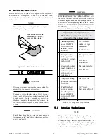
Figure 6-2 Consumable Torch Parts
2. Remove the tip. Check for excessive wear (indicated
by an elongated or oversized orifice). Replace the tip
if necessary.
NOTE
The following may also indicate a worn torch tip:
• reduced speed
• voltage drop
• crooked cut
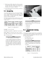
3. Remove the electrode. Refer to Figure 6-3 and check
the electrode for excessive wear. The face of the elec-
trode should not be recessed more than 1/8" (3.2 mm).
If the electrode is worn beyond this point it must be
replaced.
New Electrode
Worn Electrode
A-01270
;
Figure 6-3 Electrode Wear
4. Install the electrode, gas distributor, tip, and shield
cup in the torch body.
CAUTION
Do not overtighten the shield cup.
5. Hand tighten the shield cup using a slight twisting
motion until it is properly seated on the torch head. If
resistance is felt when installing the cup, check the
threads and parts configuration before proceeding.
7.0 PARTS
7.0 PARTS
7.0 PARTS
7.0 PARTS
7.0 PARTS
R E P L A C E M E N T
R E P L A C E M E N T
R E P L A C E M E N T
R E P L A C E M E N T
R E P L A C E M E N T
NOTE
All major parts troubleshooting, repairs, or parts
replacement should only be conducted by a quali-
fied service technician. All repairs are subject to
warranty - tampered parts may void warranty.
WARNING
Disconnect primary power to the system before dis-
assembling the torch & leads, or power supply.
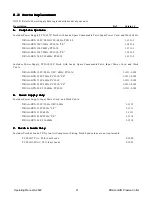
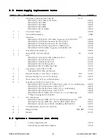
7.1 Torch & Leads Replacement
7.1 Torch & Leads Replacement
7.1 Torch & Leads Replacement
7.1 Torch & Leads Replacement
7.1 Torch & Leads Replacement
NOTE
Prior to removing leads, note all leads connections
inside the unit.
To remove the leads from the unit:
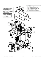
1. Disconnect the following torch lead connections in-
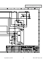
side the unit (see Appendix I):
a. 2-pin Connector
b. Faston Connector to Resistor (red)
c. Faston Connector to CD Coil (white)
2. Loosen the 90° nylon fitting nut and remove the brass
lead fitting. Remove the torch leads from unit. (Cut
lead if necessary).
3. Remove 90° nylon fitting from unit Air Compressor.
(You may need to pull the sheet metal back slightly to
do this.)
To install replacement leads:
4. Remove the securing nut from the strain relief sup-
plied on the end of the replacement torch leads.
5. Feed the end of the replacement torch lead through
the hole in the front panel.
6. Tighten the strain relief and securing nut against the
sheet metal, allowing approximately 1 inch between
the end of the lead and the strain relief nut.
7. Apply teflon thread sealant to the threads of the re-
placement 90° nylon fitting and install in correct ori-
entation as shown in Appendix I.
Содержание Drag-gun
Страница 2: ......


