Manual 0-2972
5-9
REPLACEMENT PROCEDURES
6.
Replace Housing on Cover.
7.
Attach gas supply hose.
NOTE
If unit leaks between housing and cover, inspect the
O-Ring for cuts or other damage.
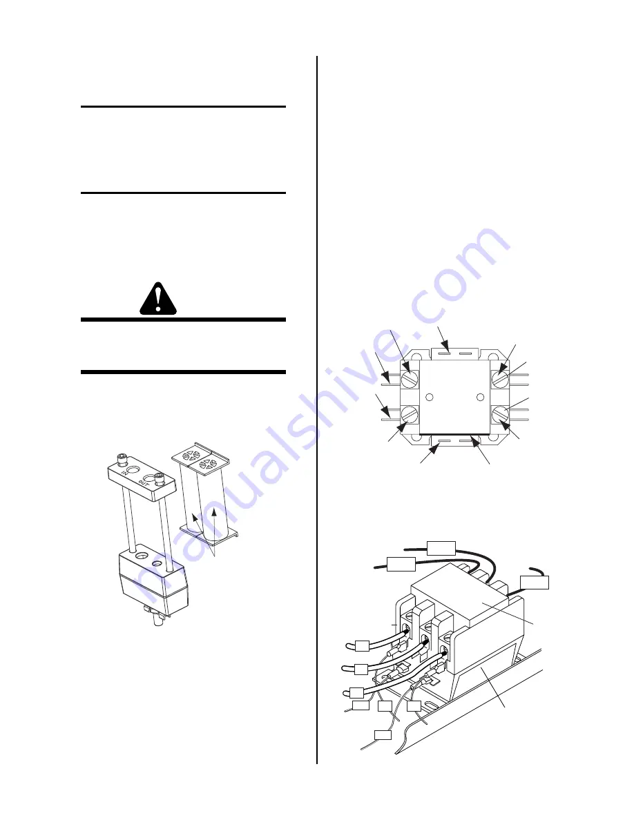
E. Optional Two-Stage Filter Element
Replacement
NOTE
The Two-Stage Air Filter has two Filter Elements.
When the Filter Elements become dirty the Power
Supply will continue to operate but cut quality may
become unacceptable.
1.
Remove power from power supply.
WARNING
Always turn off the air supply and bleed the system
before disassembling the Filter Assembly as injury
could result.
2.
Loosen the two bolts on the top of the Filter Assem-
bly enough to allow the Filter Elements to move
freely.
First & Second
Stage
Cartridges
(as marked)
Art # A-02942
3.
Slide out the old Filter Elements.
4.
Slide the replacement Filter Elements into the Filter
Assembly, with the original orientation.
5.
Hand tighten the two bolts evenly, then torque each
bolt to 20 - 30 in-lbs (2.3 - 3.4 Nm).
6.
Slowly apply air pressure to the assembly, check-
ing for leaks.
F. Input Power Cable Replacement
1.
Remove the cover per Subsection 5.04-A.
2.
Label and disconnect the wires from the Main In-
put Contactor.
3.
Remove the hardware securing the input power
ground wire to the ground stud on the base of the
unit.
4.
Unthread the retaining nut on the Input Cable
Strain Relief on the inside of the Rear Panel. Re-
move the Input Power Cable from the unit.
5.
Install the replacement Input Power Cable by re-
versing the above steps. The input cable ground
wire requires a ring terminal. Refer to the follow-
ing illustrations for wire connections.
For 208/230-Volt Power Supplies:
A-02849
Black
Cable #2
Black
Cable #1
Blue
Wire #11
Blue
Wire #12
Blue
Wire #3
Blue
Wire #4
White Input
Cable (L1)
Black Input
Cable (L2)
Label
T1
T2
For 400-Volt and 460-Volt Power Supplies:
A-03176
Main Contactor
#12
#3
L1 L2 L3
T1
T2
T3
To E3
Connections to
Main PCB
#4
L3
L2
#11
To E1
To E2
Input Side
Label
L1
Содержание 51 CUTMASTER
Страница 2: ......
Страница 4: ......
Страница 16: ...INTRODUCTION 2 2 Manual 0 2972 This Page Left Blank...
Страница 40: ...TROUBLESHOOTING 4 20 Manual 0 2972 This Page Left Blank...
Страница 65: ...Manual 0 2972 A 3 APPENDIX This Page Left Blank...
Страница 72: ...APPENDIX A 10 Manual 0 2972 APPENDIX 7 IGBT CIRCUIT PC BOARD LAYOUT A 02851 E31 TP13 TP14 E32 E28 E30 E29 E33...
Страница 73: ...Manual 0 2972 A 11 APPENDIX APPENDIX 8 INPUT DIODE PC BOARD LAYOUT Art A 03882 E18 E13 E14 E5 E16 E8 E6...
Страница 74: ...APPENDIX A 12 Manual 0 2972 APPENDIX 9 OUTPUT DIODE PC BOARD LAYOUT A 02853 E37 E36 E38 E40 E43 E42 E39 E41...
Страница 75: ...Manual 0 2972 A 13 APPENDIX This Page Left Blank...


