


Airplane Factory SLING LSA
Pilot Operating Handbook
Page | 7-21
Date of Issue: 07 July 2014
Revision : 1.3
For information about the particular engine’s integral electrical system
(alternator, ignition etc.) please refer to the applicable Rotax 912 ULS
/ 912 iS documents.
Charge system
For aircraft fitted with the 912 iS engine refer to the applicable supplement
at the end of this manual.
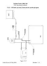
Refer to paragraph 7.17.1. The alternating current (AC) output of the
engine driven alternator is routed to a rectifier / regulator where it is
converted (rectified) and regulated, to provide direct current (DC) output
available to the aircraft systems (e.g. to charge the main battery). Charge
system output is approximately 13.5 to 14 V DC (from 1000 ±250 rpm and
higher).
The charge system output is connected to the battery / main bus via a
charge relay. Refer to paragraph 7.17.1. The charge relay coil is powered
from the main bus (i.e. needs power from the main bus to remain
energized / closed).
Loss of power to the main bus will result in the charge relay de-energizing
and disconnecting the charge system output from the battery / main bus.
Failure (i.e. with the relay contact opening) of the charge relay will
disconnect the charge system from the battery / main bus. The main bus /
system voltage (indication on EFIS) could show a reduced reading.
Alternator failure indication
For alternator failure indication / indicators on 912 iS equipped aircraft
please refer to the applicable supplement at the end of this manual.


