Airplane Factory SLING LSA
Pilot Operating Handbook
Page | 7-16
Date of Issue: 07 July 2014
Revision : 1.3
7.11
Flap and elevator trim systems
The aircraft is equipped with electric flaps and an electric elevator trim
system. The flap motor is located in the cabin center console. The two
wing flaps are interconnected via a torque tube, which is driven at a single
point by the flap motor. Bar a failure in the linkage system, this prevents
the flaps from being deployed (driven) to asymmetrical positions. Pilot
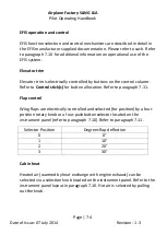
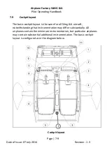
control of the flap system is via a four-position rotary knob (electronic
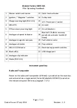
controller) located on the instrument panel. Refer to paragraphs 7.2 and
the instrument panel layout in paragraph 7.10.
The flap controller is powered from the main bus. The flap controller in
turn powers the flap motor, via a circuit breaker located on the instrument
panel (refer to paragraph 7.17.2).
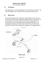
The trim motor is located in the port elevator and drives a trim tab (via a
pushrod system) located on the elevator trailing edge. Pilot control is via
buttons located on the control stick(s). Refer to paragraph 7.2 for button
allocation.
In 912 ULS equipped aircraft the trim system is powered (via a circuit
breaker located on the instrument panel) directly from the charge system
output and / or from the main bus (provided the charge relay is energized
/ not failed). Refer to paragraph 7.17.1. In 912 iS equipped aircraft the trim
system is powered from the main bus (refer to the circuit diagrams in the
applicable supplement at the end of this manual).
WARNING
The flap system becomes non-operational with loss of power to the main
bus. The elevator trim remains operational with loss of power to the main
bus, provided that the charge system remains operational.
On 912 iS equipped aircraft, the elevator trim becomes non-operational
with loss of power to the main bus.


