TFT AXD1ST-NX-F Скачать руководство пользователя страница 20

©Copyright Task Force Tips LLC 2014-2021

20

LIA-208 May 19, 2021 Rev05

8.0 MAINTENANCE

TFT  products  are  designed  and  manufactured  to  be  damage  resistant  and  require  minimal  maintenance.  However,  as  the  primary

firefighting tool upon which your life depends, it should be treated accordingly. The unit should be kept clean and free of dirt by rinsing

with water after each use. Any inoperable or damaged parts should be repaired or replaced before placing the unit in service. To help

prevent mechanical damage, do not drop or throw equipment. 
In applications where appliances are left continuously connected to the apparatus or other devices or are used where water is trapped

inside the appliance, the appliance must be flushed with fresh water following each use and inspected for damage.
This appliance should be disconnected, cleaned and visually inspected inside and out at least quarterly, or as water quality and use may

require.  Moving  parts  such  as  handles,  valve  ball  and  couplings  should  be  checked  for  smooth  and  free  operation.  Seals  shall  be

greased as needed with Silicone based grease such as Molykote 112. Any scrapes that expose bare aluminum should be cleaned and

touched up with enamel paint such as Rust-Oleum. Replace any missing or damaged parts before returning to service. 
Any equipment taken out of service due to failure should be returned to the factory for repair or replacement. If you have any questions

regarding the testing or maintenance of your valve, please call Task Force Tips at 800-348-2686. 

8.1 TROUBLESHOOTING

Table 8.1

8.2 SERVICE TESTING

In accordance with NFPA 1962, equipment must be tested a minimum of annually. Units failing any part of this test must be removed

from service, repaired and retested upon completion of the repair. 

8.3 REPAIR

Factory  service  is  available  with  repair  time  seldom  exceeding  one  day  in  our  facility.  Factory  serviced  equipment  is  repaired  by

experienced technicians, wet tested to original specifications, and promptly returned. Any returns should include a note as to the nature

of the problem and whom to reach in case of questions.
Repair parts and service procedures are available for those wishing to perform their own repairs. Task Force Tips assumes no liability for

damage to equipment or injury to personnel that is a result of user service. Contact the factory or visit the web site at tft.com for parts

lists, exploded views, test procedures and troubleshooting guides.  
Performance tests shall be conducted on the equipment after a repair, or anytime a problem is reported to verify operation in accordance

with TFT test procedures. Consult factory for the procedure that corresponds to the model and serial number of the equipment. Any

equipment which fails the related test criteria should be removed from service immediately. Troubleshooting guides are available with

each test procedure or equipment can be returned to the factory for service and testing. 

SYMPTOM

POSSIBLE CAUSE

REMEDY

Leaks

Debris or damage in seal area

Clean out debris and/or replace damaged parts

Binding, Erratic Operation

Low voltage (see below)

See Below

Power LED on but no operation

Low voltage due to:

• wire gauge too small

• wire length too long

• poor connection

• inadequate apparatus electrical 

system

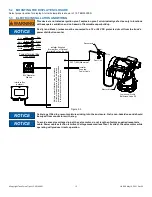
Check connections and wiring See Section 5.3.1 

on page 14.

LED D6 on motor board blinks 

rapidly when button is pressed

Loose encoder connection

Replace motor subassembly

Bad motor encoder

Replace motor subassembly

No power LED

Polarity reversed or poor connection

Check wiring and correct polarity

OPEN & CLOSE LED blink every 4 

seconds

No communication with Valve Motor

Check Blue and White communication wiring

WARNING

Service  technicians  bear  responsibility  for  ensuring  use  of  appropriate  protective  clothing  and

equipment. The chosen protective clothing and equipment must provide protection from potential

hazards users may encounter while servicing equipment. Requirements for protective clothing and

equipment are determined by the Authority Having Jurisdiction (AHJ).  

CAUTION

Any alterations to the product or its markings could diminish safety and constitutes a misuse of 

this product. 

NOTICE

All replacement parts must be obtained from the manufacturer to assure proper operation of the 

device. 

Содержание AXD1ST-NX-F

Страница 1: ...ith the operation servicing and safety procedures associated with this product This manual should be kept available to all operating and maintenance personnel LEFT DRIVE RIGHT DRIVE AXD1ST NX T Jumbo...

Страница 2: ...rns or other severe injury Fire and Emergency Manufacturers and Service Association Inc PO Box 147 Lynn eld MA 01940 www FEMSA org 2020 FEMSA All Rights Reserved PERSONAL RESPONSIBILITY CODE DANGER SU...

Страница 3: ...FSET OF THE CRANK HANDLE 5 6 CHANGING COUPLING LOCK OUT 5 7 PEG OPTION 5 8 STORZ SUCTION GASKET REQUEST 6 0 USE 6 1 ELBOW 6 2 MANUAL VALVE OPERATION 6 3 RC VALVE OPERATION 6 4 AIR VENT AND WATER DRAIN...

Страница 4: ...TION indicates a potentially hazardous situation which if not avoided could result in minor or moderate injury NOTICE NOTICE is used to address practices not related to physical injury DANGER An inade...

Страница 5: ...o 135 F 32 to 57 C Materials Used Aluminum 6000 series hard anodized MIL8625 class 3 type 2 stainless steel 300 series For temperatures below 32 0 C valves must be drained after use to avoid damage Vo...

Страница 6: ...ake Elbow Swivel Side B Coupling Valve Position Indicator Hand Crank Outlet Side A Coupling AZD1ST NX T Left Drive Jumbo Low Profile Ball Intake Valve Top Crank with Pressure Relief Valve Manual Overr...

Страница 7: ...ith salt water is permissible provided the equipment is thoroughly cleaned with fresh water after each use The service life of the equipment may be shortened due to the effects of corrosion and is not...

Страница 8: ...sition 6 9 174mm 6 8 172mm 8 4 213mm 6 9 174mm 6 8 172mm 8 4 213mm R3 4 R87 SWING R3 4 R87 SWING 11 3 286mm 8 7 221mm 7 2 183mm 5 6 142mm 5 6 142mm 12 2 309mm 7 2 183mm 9 4 240mm Top View Angled Posit...

Страница 9: ...Position 12 3 312mm 5 6 142mm 4 8 122mm 8 7 221mm 8 4 213mm 6 8 172mm R3 4 R87 SWING 7 0 178mm 5 6 142mm 4 8 122mm 9 4 240mm 8 4 213mm 6 8 172mm 7 0 178mm R3 4 R87 SWING Front View Down Position Fron...

Страница 10: ...122mm 8 7 221mm R3 4 R87 SWING 6 9 174mm Front View Down Position 8 4 213mm 6 8 172mm R3 4 R87 SWING Front View Angled Position 6 9 174mm 4 8 122mm 9 4 240mm 12 3 312mm 5 6 142mm Side View Down Positi...

Страница 11: ...View Down Position 6 8 172mm 8 8 223mm 6 8 172mm 8 8 223mm 4 8 122mm 9 4 240mm 10 5 267mm 5 6 142mm 10 5 267mm 11 3 286mm 5 6 142mm 4 8 122mm 8 7 221mm Side View Angled Position Side View Down Positio...

Страница 12: ...led together can cause galvanic corrosion that can result in the inability to uncouple the connection or complete loss of engagement over time Failure could cause injury Per NFPA 1962 if dissimilar me...

Страница 13: ...Gel is non hazardous and should be wiped from conductors with a rag NOTICE To avoid excessive voltage drop at the valve motor do not lengthen factory supplied receptacle cable Power cable selection is...

Страница 14: ...stop by current limit method A If motor continues to operate see proper voltage test above 4 Position indicator lights will now track valve movement 5 4 BIV RC MANUAL OVERRIDE The Ball Intake Valve R...

Страница 15: ...ime swivel to rigid 1 Align the pull pin in the elbow to vertical 2 Rotate the coupling until the lockout screw is aligned with the pull pin 3 Use a 7 32 hex driver to tighten the lockout screw into t...

Страница 16: ...will reach the positive stops when the handle is either parallel to the outlet OPEN position or perpendicular to the outlet CLOSED position Valves with hand cranks include a valve position indicator...

Страница 17: ...s equipped with an air vent drain o the front of the unit which will allow the air to escape from the valve when the hose is charged The air vent drain is opened by turning the knob counter clockwise...

Страница 18: ...mits The pressure relief valve meets the requirements of NFPA 1901 6 6 PRESSURE LOSS Figure 6 6 6 7 SUCTION SCREEN This device may be equipped with a suction screen to catch debris larger than 3 8 dia...

Страница 19: ...less reasonable depreciation in complete discharge of its obligations under this limited warranty If TFT makes this election claimant shall return the equipment to TFT free and clear of any liens and...

Страница 20: ...as to the nature of the problem and whom to reach in case of questions Repair parts and service procedures are available for those wishing to perform their own repairs Task Force Tips assumes no liab...

Страница 21: ...6 If crankshaft rotates freely after clearing any obstructions a replacement crank shaft may be ordered from Task Force Tips and replaced as described below 8 4 3 CRANKSHAFT REPLACEMENT A broken crank...

Страница 22: ...ce 11 There are no missing worn out or broken lugs on couplings 12 Hose is securely attached BEFORE BEING PLACED BACK IN SERVICE equipment must be inspected to this list 1 All valves open and close sm...

Страница 23: ...Copyright Task Force Tips LLC 2014 2021 23 LIA 208 May 19 2021 Rev05 This page intentionally left blank...

Страница 24: ...ATES 11 1 DISPLAY ENCLOSURE Figure 11 1 11 2 QUICK CONNECT PLUG Figure 11 2 HOLE LOCATIONS FOR BIV RC POSITION DISPLAY 7 32 5 5mm DIA 4 PLACES OR TAP FOR 10 32 UNC THREAD 3 1 2 89mm 3 1 2 89mm MOUNT E...

Отзывы: