


©Copyright Task Force Tips LLC 2014-2021
14
LIA-208 May 19, 2021 Rev05
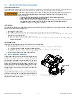
5.3.1 TESTING THE ELECTRICAL INSTALLATION
VERIFY PROPER VOLTAGE
The TFT Ball Intake Valve RC has built in circuit protection to guard against a circumstance where the unit’s movement is blocked before
reaching its full travel limits. Without this circuitry the motor would stall, overheat, and could be permanently damaged.
VOLTAGE TEST
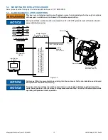
When mechanical installation and electrical connections are complete, perform the following test to verify voltage supply is adequate
and the current limiting feature is functioning.
1. Apply power to Valve Control.
2. Press OPEN or CLOSE button and hold until valve reaches stop position. Continue to hold button down.
3. Once movement is stopped, manually turn override knob in opposite direction while continuing to hold button down. (The override
knob will only turn in one direction.
A. If knob can be turned, then voltage supply is adequate.
B. If knob can’t be turned and motor continues to operate, the current limit was not reached because the voltage supply or
wiring is not adequate.
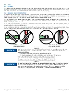
SET TRAVEL STOPS
Once proper voltage is verified, perform the following to set the full travel limits:
1. Apply power to Valve Control.
2. Press CLOSE button and continue to hold until valve is fully closed. Motor must stop by current limit method.
A. If motor continues to operate, see proper voltage test above.
3. Press OPEN button and continue to hold until valve is fully open. Motor must stop by current limit method.
A. If motor continues to operate see proper voltage test above.
4. Position indicator lights will now track valve movement.
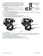
5.4 BIV RC MANUAL OVERRIDE
The Ball Intake Valve RC is motor driven but also has an override
handwheel for operating the valve manually. The override
handwheel may also be used in the event of power failure. If
electrical power is supplied to the control panel, the LED valve
position display will track the valve’s position as the handwheel is
moved. If the handwheel is moved while there is no power to the
electric controls, the LED valve position display will be in error
when the electric power is reconnected. The LED valve position
indicator will self correct the first time the valve is cycled under
electric control.
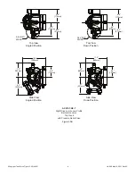
If more compactness is desired, the override handwheel may be
removed. The drive shaft has a hex so a wrench or socket may
be used for manual override. If the manual override handwheel is
removed, assure that the correct size wrench or socket is
available in the event of power failure.
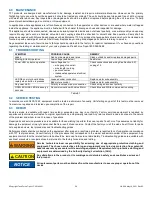
WARNING
Inadequate voltage cause the valve to become damaged to the point of inability to properly open or
close, resulting in inadequate water supply. Injury or death can occur. To reduce the risk of
improper voltage:
• Check wiring for proper gauge for the installed length, and for proper termination.
• Never lengthen factory supplied receptacle cable.
• Ensure that the power source supplying the BIV RC and the grounding are adequate (other
electrical loads on a shared circuit with the BIV RC may cause a low-voltage situation).
• ALWAYS test for proper voltage after installation.
11/16" [18 mm] Hex
Remove Screws
Figure 5.4