


©Copyright Task Force Tips LLC 2014-2021
17
LIA-208 May 19, 2021 Rev05
6.3 RC VALVE OPERATION
Power LED:
• LED will be solid green when power is present
Position Indicator:
• 5 LEDs indicate valve position. One for full close (red at far right), one
for full open (green at far left), three yellow for 25%, 50%, and 75%
open. Two LEDs will light when position is between two percentages.
• The position indicator will lose position if the manual override is used
while the power is off. Position location is restored after the first cycle
of electric operation.
• All 5 position LED’s blinking indicates a fault with the motors encoder.
Control Buttons:
Manual Mode
• When OPEN or CLOSE button is pressed, valve opens or closes until
button is released.
Automatic Mode
• When OPEN or CLOSE button is momentarily pressed, valve opens or
closes fully.
• During valve movement if STOP or the other direction is momentarily
pressed the motor will stop.
Changing Modes (Unit is shipped from factory in the Auto Mode)
• Press CLOSE and STOP buttons together and hold for 3 seconds to
change to Automatic Mode.
• Press OPEN and STOP buttons together and hold for 3 seconds to
change to manual mode.
To Reverse Polarity (direction) of the Motor
• Press OPEN and CLOSE buttons together and hold for 15 seconds.
6.4 AIR VENT AND WATER DRAIN
This device is equipped with an air vent/drain o the front of the unit which will allow the air to escape from the valve when the hose is
charged. The air vent/drain is opened by turning the knob counter-clockwise and closed by turning it clockwise.
There is a second plugged port on the top of the valve. To use a different port position, relocate the factory supplied Air Vent/Drain Valve
or install an additional Air Vent/Drain Valve. If the Air Vent/Drain Valve is being relocated, use a ¾” NPT plug to seal the empty port.
6.5 PRESSURE RELIEF VALVE (PRV)
LDH valved appliances may be equipped with a pressure relief valve that can be set to any pressure between 90 and 300 psi. Its
function is to protect the pump and supply hose from excess pressure.
An optional threaded outlet is available for connecting a hose to discharge opening to direct water away from valve. Contact the factory
to order.
• A1114NFM-KIT - 1.5” NH Male Outlet
• A1114TFM-KIT - 1.5” NPT Male Outlet
See LIA-202 Pressure Relief Valve Instructions for Safe Operation and Maintenance.
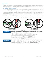
CAUTION
Loss of prime can interrupt water flow and cause injury or death. Always bleed out air with air
vent/drain to prevent possible loss of prime.
WARNING
The Pressure Relief Valve is disabled in the OFF position and offers no system protection against
over-pressurization. Avoid water hammer or other pressure spikes during pump tests. Ensure PRV
is returned to its normal pressure setting following pump testing.
POWER
LED
POSITION
INDICATOR
CONTROL BUTTONS
Figure 6.3