


©Copyright Task Force Tips LLC 2014-2021
5
LIA-208 May 19, 2021 Rev05
3.1 SPECIFICATIONS
3.1.1 MECHANICAL
Table 3.1.1
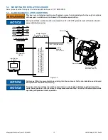
3.1.2 ELECTRICAL
Table 3.1.2
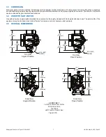
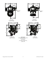
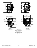
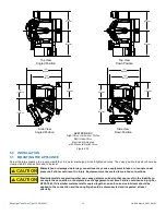
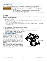
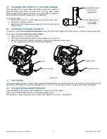
3.2 VARIOUS MODELS AND TERMS
Figure 3.2A
STANDARD
METRIC
LDH Waterway Size (at valve seat)
5.25”
133 mm
LDH Valve Meets NFPA Slow Close Requirement
Maximum Operating Pressure
250 psi
17 bar
Minimum Pressure
Full Vacuum
Hydrostatic Proof Test Pressure
900 psi
62 bar
Operating Temperature Range of Fluid
33° to 120°F
0° to 50°C
Storage Temperature Range*
-25° to 135°F
-32° to 57°C
Materials Used
Aluminum 6000 series hard anodized MIL8625 class 3
type 2, stainless steel 300 series
* For temperatures below 32° (0°C), valves must be drained after use to avoid damage.
Voltage - Auto Sense
12 Volt
24 Volt
Motor Opening/Closing Speed
6 seconds
Motor Current - Nominal
3 amp
1.5 amp
Motor Current - Limit
12 amp
6 amp
Recommended Fuse Size
15 amp
7.5 amp
Environmental Rating
All components designed to meet minimum rating of
NEMA 4 (IP65)
Hand Crank
Pressure Relief Valve
Air Vent & Drain
Pull Pin
Intake Elbow
Swivel Side B Coupling
Valve Position
Indicator
Outlet
Side A Coupling
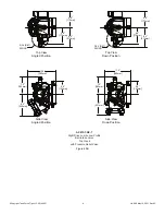
AXD1ST-NX-F
Left Drive Jumbo Low Profile
Ball Intake Valve
Front Crank
with Pressure Relief Valve