


4
2 February, 2005 Code Sheet V4.01d (NZ1001)
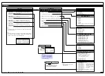
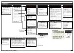
Tiger 380 Series Code Logic Diagram
To enter press the
and
buttons at the same time
Calibration Modes for Inputs and Outputs
Code 1 – Display Configuration
Code 2 – Sampling Rate & CH1 Measurement Task
Code 3 – CH1 Post Processing Functions
Code 4 – CH2 Functions
Code 5 – CH3 Functions
Code 6 – CH4 Functions
Code 7 – Result Processing
Code 8 – Data Logging & Printer Options
Code 9 – Functions for Digital Input Pins
[ CAL ]
[CODE_1]
[CODE_2]
[CODE_3]
[CODE_4]
[CODE_5]
[
CODE_6]
[CODE_7]
[CODE_8]
[CODE_9]
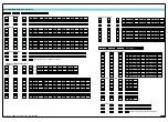
To enter press the
and
buttons at the same time
Setpoint 1
[SP_1]
Setpoint Activation Values Mode
Setpoint 2
[SP_2]
Setpoint 3
[SP_3]
Setpoint 4
[SP_4]
Setpoint 5
[SP_5]
Setpoint 6
[SP_6]
Enter these menus to set setpoint
(SP) activation values
Setpoint 1
[SPC_1]
Setpoint & Relay Control Settings Mode
Setpoint 2
[SPC_2]
Setpoint 3
[SPC_3]
Setpoint 4
[SPC_4]
Setpoint 5
[SPC_5]
Setpoint 6
[SPC_6]
Enter these menus to configure SP control
settings
See Pages 5 to 7 for calibration settings to perform the following calibration functions
on input and output signals (The first 5 functions are activated by pressing Prog.):
See Page 8 for code settings to configure:
See Page 9 for code settings to configure the following:
• Analog sampling rate and control output rate for all seven channels.
• CH1 Measurement task (input signal type and range selection for CH1).
See Page 10 for code settings to configure the following CH1 post processing
functions:
• Direct signal, square root, or inverse of CH1.
• Apply selected linearization table to CH1 signal.
See Page 10 for code settings to configure CH2 when using dual input
signal conditioners:
• Direct signal, square root, or inverse of CH2 voltage or current input.
• CH2 Measurement task (input signal type and range selection for CH2).
• Apply selected linearization table to CH2 signal.
See Page 11 for code settings to configure data logging and data print-
ing from the controller.
See Page 11 for code settings to configure the inputs from external
sources through the following digital input pins on the rear of the con-
troller:
• Display test pin.
• Hold pin.
• Lock pin.
The
Setpoint and
Relay Control
Settings
diagram
on Pages 12 to 14
shows the three
digit configuration
settings that are
applied individually
to each setpoint.
Display Brightness
[ BRI ]
Allows you to adjust the display brightness in a range of 8 settings. 0 being dull,
7 being bright.
Main Programming Mode
Setpoint Programming Mode
Prog.
SP1
SP2
SP4
SP3
SP5
SP6
OPERATIONAL DISPLAY
Prog.
SP1
SP2
SP4
SP3
SP5
SP6
OPERATIONAL DISPLAY
Default setting = 18000
Default setting = –18000
Default setting = 5000
Default setting = –5000
Default setting = 10000
Default setting = –10000
• Tare.
• Single point auto calibration.
• 2-point auto calibration.
• Primary input compensation.
• Manual loader.
• Manual calibration.
• 2-point calibration.
• Thermocouple calibration.
• RTD calibration.
• Set up serial output.
• Set up auto zero maintenance settings.
• Set up averaging samples & averaging window.
• Set K factor & cutoff for totalizers.
• Set up four 32-point linearization tables.
• Analog output scaling.
• Tendency indication thru SP1 & SP2 annunciators (shows rising / falling signal).
• Indication of setpoints / relays operation thru dedicated annunciators.
• Selecting the data source for the display and peak / valley 1 to 3.
• Selecting last digit rounding.
• Selecting display units.
• Selecting decimal point position.
• Display manual loader.
• Display with selected update rates (display shows selected register).
See Page 10 for code settings to configure CH3 when using triple input
signal conditioners:
• Direct signal, square root, or inverse of CH3 voltage or current input.
• CH3 Measurement task (input signal type and range selection for CH3).
• Apply selected linearization table to CH3 signal.
See Page 11 for code settings to configure CH4 when using quad input
signal conditioners:
• Direct signal, square root, or inverse of CH4 voltage or current input.
• CH4 Measurement task (input signal type and range selection for CH4).
• Apply selected linearization table to CH4 signal.
See Page 11 for code settings to configure the controller for processing
the result of CH1 and CH2:
• Direct signal, square root, or inverse of Result signal.
• Apply selected linearization table to Result signal.
• Maths functions for Result (CH1and CH2).


