


17
2 February, 2005 Code Sheet V4.01d (NZ1001)
201
BAUD
PARITY
ADDRESS
MODE
1st DIGIT
2nd DIGIT
3rd DIGIT
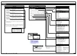
CALIBRATION MODE [CAL] Continued
SUB-SETTINGS
RELATED CALIBRATION FUNCTIONS
202
BAUD
PARITY
ADDRESS
MODE
Serial Output
Auto Zero Maintenance
210 AZ CAPTURE
AZ MOTION
AZ APERTURE
211 AZ CAPTURE
AZ MOTION
AZ APERTURE
212 AZ CAPTURE
AZ MOTION
AZ APERTURE
213 AZ CAPTURE
AZ MOTION
AZ APERTURE
214 AZ CAPTURE
AZ MOTION
AZ APERTURE
Averaging Samples & Averaging Window
220 AVERAGE SAMPLES
AVERAGE WINDOW
241
MODE
251 ZERO
FULL SCALE
221 AVERAGE SAMPLES
AVERAGE WINDOW
222 AVERAGE SAMPLES
AVERAGE WINDOW
223 AVERAGE SAMPLES
AVERAGE WINDOW
224 AVERAGE SAMPLES
AVERAGE WINDOW
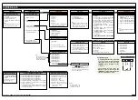
Totalizer
32-point Linearization Tables
242
MODE
243
MODE
244
MODE
245
MODE
Scale Analog Output
252 ZERO
FULL SCALE
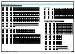
121
ZERO
SPAN
151
CAL LOW
CAL HIGH
INPUT
INPUT
Calibrate Thermocouple
122
ZERO
SPAN
INPUT
INPUT
123
ZERO
SPAN
INPUT
INPUT
OUTPUT
OUTPUT
Calibrate Analog Output
152
CAL LOW
CAL HIGH
OUTPUT
OUTPUT
SOURCE
SOURCE
1st DIGIT
2nd DIGIT
3rd DIGIT
SUB-SETTINGS
TC TYPE
UNITS
TC TYPE
UNITS
TC TYPE
UNITS
121
ZERO
SPAN
INPUT
INPUT
Calibrate RTD
122
ZERO
SPAN
INPUT
INPUT
123
ZERO
SPAN
INPUT
INPUT
RTD TYPE
UNITS
RTD TYPE
UNITS
RTD TYPE
UNITS
124
ZERO
SPAN
INPUT
INPUT
125
ZERO
SPAN
INPUT
INPUT
126
ZERO
SPAN
INPUT
INPUT
RTD TYPE
UNITS
RTD TYPE
UNITS
RTD TYPE
UNITS
127
ZERO
SPAN
INPUT
INPUT
RTD TYPE
UNITS
153
215 AZ CAPTURE
AZ MOTION
AZ APERTURE
216 AZ CAPTURE
AZ MOTION
AZ APERTURE
217 AZ CAPTURE
AZ MOTION
AZ APERTURE
225 AVERAGE SAMPLES
AVERAGE WINDOW
226 AVERAGE SAMPLES
AVERAGE WINDOW
227 AVERAGE SAMPLES
AVERAGE WINDOW
AFTER
CUTOFF
TOTAL
R_OVER
AFTER
CUTOFF
TOTAL
R_OVER
AFTER
CUTOFF
TOTAL
R_OVER
SOURCE
INPUT
SOURCE
INPUT
SOURCE
INPUT
231
232
233
246
MODE
247
MODE
253
Analog output 3 [253] to 7 [257] Not yet available
Port 1
Port 2
Analog output 3 [153] to 7 [157] Not yet available
203
BAUD
PARITY
ADDRESS
MODE
Port 3
AFTER
CUTOFF
TOTAL
R_OVER
AFTER
CUTOFF
TOTAL
R_OVER
AFTER
CUTOFF
TOTAL
R_OVER
SOURCE
INPUT
SOURCE
INPUT
SOURCE
INPUT
234
235
236
AFTER
CUTOFF
TOTAL
R_OVER
SOURCE
INPUT
237


