www.ti.com
Board Setup and Operation
4
Board Setup and Operation
4.1
Board Setup
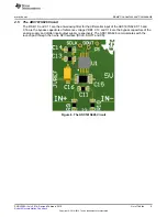
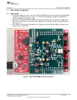
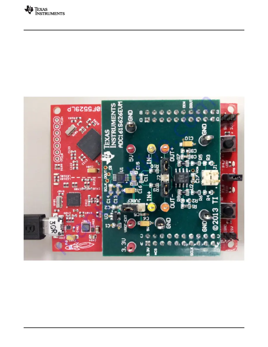
1. The female headers JA, JB, JC, and JD on ADC161S626EVM should be connected with the MSP430
Launch Pad correctly as shown in
Figure 13
. The ADC161S626EVM is supplied by the MSP 430
Launch-Pad through 5 V and 3.3 V pins.
2. By default, the ADC161S626EVM JVREF should be jumped for pin2-3. This allows the VREF of the
ADC to be sourced from an on-board 4.096 V regulator. The user can also use an external VREF by
shorting pin1-2.
3. The outputs of the differential amplifier are connected with inputs of ADC161S626 by shorting pin1-2
and pin 4-5 on J2 by default.
Figure 13. ADC161S626EVM Hardware Connection
15
SNOU130A – July 2014 – Revised February 2015
List of Tables
Submit Documentation Feedback
Copyright © 2014–2015, Texas Instruments Incorporated


