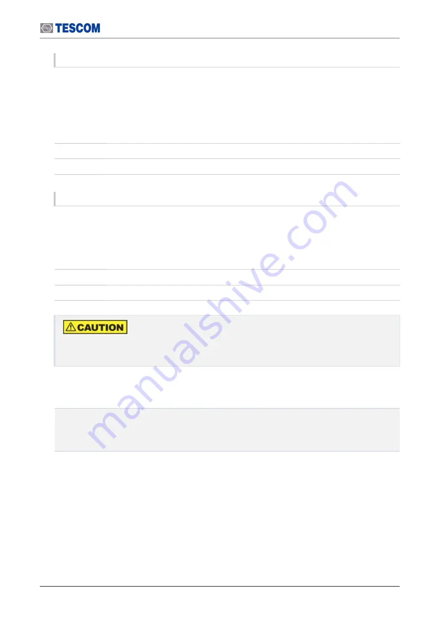
background image

RS-232C Commands

35

DUAL HAND ON

A command to set the Lid OPEN/CLOSE motion in Dual Hand Mode.

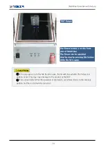
Two buttons on both sides of the control box must be pressed simultaneously to close the lid. Either

one of the two buttons works to open the lid.

Type

Command

Input

DUAL HAND ON

Response

OK

DUAL HAND OFF

A command to turn the Dual Hand Mode off.

Only one button on the

right hand side

will work to open/close the lid.

Type

Command

Input

DUAL HAND OFF

Response

OK

It is strongly recommended to use the Dual Hand Mode unless absolutely unnecessary. The

other hand may be trapped if the mode is off.

5.7.2.2 Probe Configuration Commands

SOLENOID MODE?

PROBE MODE TIMER

PROBE MODE OFF

Содержание TC-5910DP

Страница 1: ...TC 5910DP Pneumatic Shield Box User Manual R20191023...

Страница 2: ...Copyright 2019 TESCOM CO LTD ALL RIGHTS RESERVED Address 10442 927 Unitechvil 142 Ilsan ro Ilsandong gu Goyang si Gyeonggi do TEL 82 31 920 6600 HOMEPAGE www tescom co kr...

Страница 3: ...ice PART 2 Hardware Description 2 Hardware Overview 2 1 Component Identification 2 2 Dimensions 3 Optional Panels Fixture 3 1 I O Interface Panels 3 2 Fixtures PART 3 Putting into Operation 4 Setup an...

Страница 4: ...h Terminal Application on PC 5 5 RS 232C Command List 5 6 Error Data List 5 7 RS 232C Commands PART 4 Maintenance 6 Maintenance 6 1 Maintenance 6 2 Performance Test 7 Expendables and Accessories 7 1 E...

Страница 5: ...Revision History v Revision Record Revision Description Date v1 0 Initial Release 2019 10 31 v1 1 Minor Fix 2019 11 04 v1 2 Photo Change 2019 12 04...

Страница 6: ...s warranty does not apply to Expendables and Accessories and any failure or damage caused by improper use or unauthorized service In such cases TESCOM may refuse to offer any service under the warrant...

Страница 7: ...ate in explosive atmosphere To avoid injury or fire hazard do not operate this product in an explosive atmosphere Provide proper ventilation To prevent product overheating provide proper ventilation D...

Страница 8: ...es that could result in damage to the product or other property Symbols The following symbols may appear in this manual or on the product Symbol Meaning Crush hazard Moving part can cause serious inju...

Страница 9: ...PART 1 1 Getting Started...

Страница 10: ...Key Features Reliable RF shielding up to 6 GHz Pneumatic control of lid open close and diverse fixture motions EMI filter on all data ports and power line Suitable for various tests to satisfy custome...

Страница 11: ...Shielding effectiveness dB 100 to 2000 MHz 70 dB 2000 to 3000 MHz 70 dB 3000 to 6000 MHz 60 dB 1 3 Initial Inspection When TC 5910DP is delivered inspect the package and its content as follows 1 Check...

Страница 12: ...ve difficulty with the product call or write to our Technical Support specialists at TESCOM Company Limited 927 Unitechvil 142 Ilsan ro Ilsandong gu Goyang si Gyunggi do Korea ZIP 10442 TEL 82 31 920...

Страница 13: ...PART 2 5 Hardware Description...

Страница 14: ...1 TC 5910DP Component Identification No Name No Name 1 Lid 9 Air Cylinder 2 Lid Handle 10 Lid Close Sensor 3 Lid Open Close Button 11 Hinge 4 Power ON OFF Switch 12 I O Interface Panel 5 Green LED for...

Страница 15: ...re Air Ports Figure 2 2 TC 5910DP Fixture Air Ports Table 2 2 TC 5910DP Fixture Air Ports No Name 1 Probe UP Air Port 4 Speed control function excluded 2 Probe DOWN Air Port 4 Speed control function e...

Страница 16: ...P15 FAIL LED Connector 4 JP14 PASS LED Connector 5 JP13 TEST LED Connector 6 Solenoid Valve JP10 Solenoid Valve Connector for Probe 7 JP9 Solenoid Valve Connector for Lid JP8 Solenoid Valve Connector...

Страница 17: ...Dimensions 9 2 2 Dimensions 2 2 1 Outer Dimensions...

Страница 18: ...10 Dimensions 2 2 2 Inner Dimensions...

Страница 19: ...nd SMA f inside One 1 DB25 p outside and DB25 s inside 1000 pF Pi filter One 1 USB 2 0 outside and inside Data Interface Panel M591016B M591016E Two 2 N f outside and SMA f inside One 1 DB9 p outside...

Страница 20: ...own I O interface panel Table 3 2 Custom I O Interface I O Interface Order Number Transmission Speed Line Voltage Typical Shielding DB25 1000pF pi Filter 3409 0009 1 3 Mbps 100 VDC 5 Amps max 70 dB f...

Страница 21: ...or 3406 0004A 50 VDC 3 Amps max 70 dB from 0 5 to 2 GHz 80 dB from 2 to 3 GHz 80 dB from 3 to 6 GHz DC Power Adaptor Banana Jack Type 3406 0004A 3406 0006A 50 VDC 10 Amps max 70 dB from 0 5 to 2 GHz 8...

Страница 22: ...n a few seconds In addition custom fixtures can be ordered and supplied to suit your needs 3 2 1 Standard Grid Fixture Table 3 3 TC 5910DP Standard Grid Fixture Grid Fixture Order Number Description F...

Страница 23: ...PART 3 15 Putting into Operation...

Страница 24: ...e and check whether the following accessories are included Exterior and Accessory Inspection 1 Upon receiving the TC 5910DP check for any damages that could have occurred during shipment 2 Referring t...

Страница 25: ...m 1 5 9703 0074 Air Coupler CPS15 6W 1 6 C5910DP 0001 Cylinder Lock 1 In case of any abnormality do not install or operate Shield Box for your own safety Please contact TESCOM immediately 4 2 Operatin...

Страница 26: ...upplies power to Shield Box 3001 0039 1EA 2 Data DB9 p DB9 s 2m Connects Shield Box to PC for control 4003 0025 1EA 3 Air Coupler Main air inlet 6 mm OD hose 5 10 bar 9703 0074 1EA 4 3 1 Power Supply...

Страница 27: ...l glow white when the power is on 4 3 2 Compressed Air Supply Please make sure to turn off compressed air supply before connecting or disconnecting air hose Compressed Air Requirement Input air pressu...

Страница 28: ...compressed air inlet port is located at the TC 5910DP rear panel 2 Insert the 6 mm Air Hose to the rear point of Air Coupler 3 Push the front side of Air Coupler on Air Input Connector until you hear...

Страница 29: ...buttons simultaneously on both sides of the control box A red light will blink on the lid closing sensor An orange light will glow at the TEST LED on the front control box when the lid is fully closed...

Страница 30: ...TC 5910DP will return the number in 8 digits 4 3 4 PASS FAIL LED Indicator Green and red LED indicators will be on if the command PASS or FAIL is sent through RS 232C while the lid is closed This func...

Страница 31: ...omatic according to the open or close of Shield Box The operation of fixture can be controlled with commands via RS 232C Refer to the list of commands and each command in detail at 5 7 2 2 Probe Confi...

Страница 32: ...while the lid is open the lid will close whether the fixture is in position or not This may cause damage to the product or the DUT 2 If any sensor detects that the operation is incomplete everything...

Страница 33: ...r hose The air hose for fixture is 4 mm outside diameter hose 1 Open the TC 5910DP control box 2 Locate the air hose for Probe Figure 4 5 Air Ports and Fittings for Fixture 3 Remove the fitting plug a...

Страница 34: ...th all Probe air hoses connected it will look like below Figure 4 7 TC 5910DP Fixture Connection Figure 7 above is just a recommendation so the actual connection may be adjusted for your convenience T...

Страница 35: ...the fixture mode must be set to Off Mode Refer to 5 7 2 2 Probe Configuration Commands If the fixture mode is set to Sensor Mode sensors will detect nothing and thus the lid will stay open as if there...

Страница 36: ...RS 232C 5 1 RS 232C Cable Connection Connect RS 232C Cable to RS 232C DB9 Connector on the rear side of Shield Box RS 232C Port on Shield Box is a DB9 Connector Female so DB9 Data Cable DB9 p to DB9 s...

Страница 37: ...Protocol 5 3 1 Transmission Protocol 1 Every time a command is sent from PC to Shield Box a CR Carriage Return Wr 0x0D is sent at the end of it Command r 0x0D 2 When a command is sent a response Resp...

Страница 38: ...eld Box using a communication software Terminal The application is free to download from here https sites google com site terminalbpp Before beginning set everything up in 4 3 Connecting Setting Up ch...

Страница 39: ...PC 31 4 Send a command and get a response 1 Enter MODEL on the command prompt and check CR then press Send 2 A response the model name and the firmware version will appear on Receive window 3 Check th...

Страница 40: ...the Dual Hand Mode off Configuration Probe SOLENOID MODE Handler xxx Probe xxx xxx OFF TIMER SENSOR Check Handler and Probe Mode PROBE MODE TIMER OK Set Probe Mode to Timer Mode PROBE MODE OFF OK Set...

Страница 41: ...rrent status ERR50 Lid Open Sensor error It occurs only to certain products which should always detect whether the lid is open The response comes when the sensor does not detect open lid ERR60 Safety...

Страница 42: ...er the lid or fixture operation mode is changed resulting in opening the lid If the lid is already open it will pop open amid closing motion 5 7 2 1 Lid Button OPEN CLOSE Configuration Commands DUAL H...

Страница 43: ...lid Type Command Input DUAL HAND ON Response OK DUAL HAND OFF A command to turn the Dual Hand Mode off Only one button on the right hand side will work to open close the lid Type Command Input DUAL H...

Страница 44: ...w is how to change the Probe Mode from Off to Timer SOLENOID MODE Handler OFF Probe OFF PROBE MODE TIMER OK Handler is set to the Off Mode since TC 5910DP can only use the Probe PROBE MODE TIMER A com...

Страница 45: ...en If the lid does not open while the OPEN command is sent and OK response comes back check the compressed air supply CLOSE A command to close the lid The Lid Close Sensor on a cylinder will glow red...

Страница 46: ...Response OPEN CLOSE OPEN Lid opened CLOSE Lid closed 5 7 4 Probe Operation Commands PROBE UPWARD DOWNWARD PROBE A query to check the current status of the Probe Type Query Input PROBE Response UPWARD...

Страница 47: ...PWARD command is sent while the lid is closed ERR90 The command is sent while the Probe is in Off Mode DOWNWARD A command to lower the Probe down Type Command Input DOWNWARD Response OK ERR30 ERR40 ER...

Страница 48: ...utomatically Type Command Input PASS Response OK ERR40 OK turns the green PASS LED on and the lid opens ERR40 Status Error The command is sent while the lid is open FAIL A command that demonstrates wh...

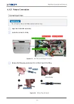
Страница 49: ...PART 4 41 Maintenance...

Страница 50: ...for Maintenance Check for loose screws and tighten with proper tools if necessary Check for a loose connection If a loose connector is found tighten the connector with proper tools Check for a damage...

Страница 51: ...e of lid contacting area can significantly reduce the effectiveness of the Shield Box This section describes the test and calibration procedure for the Pneumatic Shield Box Performance test should be...

Страница 52: ...cy Shielding effectiveness dB 100 to 2000 MHz 70 dB 2000 to 3000 MHz 70 dB 3000 to 6000 MHz 60 dB The shielding effectiveness above is measured with blank panels other I O interface panels may result...

Страница 53: ...ectrum analyzer and signal generator on 2 Using an RF cable connect the RF Connector N Type on the rear side of TC 5910DP Shield Box to the RF output port N Type of signal generator 3 Open the Shield...

Страница 54: ...tton on the spectrum analyzer to set the maximum value of measurement standard Figure 6 3 Searching for Maximum Reception 8 Close the lid 9 Set the input range of the spectrum analyzer as follows Cent...

Страница 55: ...hield Box or the lid 11 See if the difference between the measurement standard a and the maximum leakage b is within the specification Shielding Effectiveness of the product Figure 6 5 Spectrum Analyz...

Страница 56: ...s and Accessories Below is the list of expendables and accessories Please note that these items are NOT under warranty Table 7 1 List of Expendables Accessories No View Part designation Order number Q...

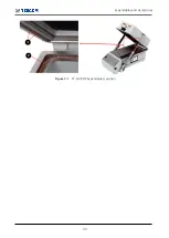
Страница 57: ...Expendables and Accessories 49 Figure 7 1 TC 5910DP Expendables Location...

Страница 58: ...hat the power cord is connected to the product and the switch is on Verify that the power supply is not short or out Verify that the line voltage is within range of 100 240 VAC Compressed Air Check Ch...

Отзывы: